Table of Contents
Advertisement
Quick Links
Advertisement
Table of Contents

Related Manuals for Pulse Instruments System 4

Summary of Contents for Pulse Instruments System 4
-
Page 5: Table Of Contents
Pulse Instruments System 4 Manual Version 1.6 Table of Contents OVERVIEW ......................3 ........................3 NTRODUCTION ........................4 EATURES SYSTEM LAYOUT ....................5 SPECIFICATIONS ....................9 ....................10 YSTEM OMPONENTS PLC I ...................10 NPUTS AND UTPUTS FUNCTION ......................11 ........................11 PERATION .........................12 ONITORING ........................12... - Page 6 Pulse Instruments System 4 Manual Version 1.6 CONFIGURATION / SETUP ................18 ........................18 OWER ........................19 OINTS ......................20 EMPERATURE 6.3.1 Setup Temperature Sensor Type ..................20 6.3.2 Setup Temperature Unit ......................20 6.3.3 Setup Analog Output Mode ....................20 6.3.4 Setup Analog High and Low Range ..................21 6.3.5...
-
Page 7: Overview
Pulse Instruments System 4 Manual Version 1.6 Overview Introduction Wash Water Sanitation by ORP for Fruits and Vegetables Introduction: In the ever-increasing need and awareness for food safety and HACCP, Water has become a focus point for proper disinfection treatment as pathogens and harmful microorganisms can become a danger for contamination of fresh fruits and vegetables during growing and post harvest contact. -
Page 8: Features
Pulse Instruments System 4 Manual Version 1.6 Process Meters: Used in a fixed location for continuous monitoring of ORP and provides a highly reliable up to date measurement as conditions continuously change in most process water applications. These instruments may also be used as a source of reading only and manually dosing chemicals, however continuous monitoring instruments are commonly used to automatically inject sanitizer on demand, and provide a reliable method of process control as well as recording for automated record keeping. -
Page 9: System Layout
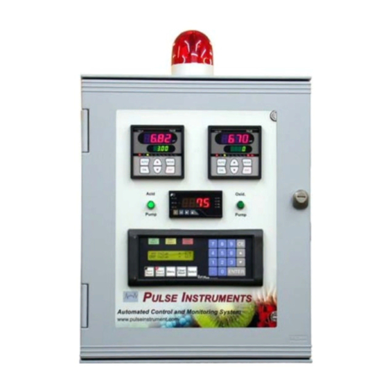
Pulse Instruments System 4 Manual Version 1.6 System Layout Fig. 1 Automation of Wash Water Sanitation System Diagram Visit us Online at www.pulseinstrument.com... - Page 10 Pulse Instruments System 4 Manual Version 1.6 Fig. 2 Operator Interface Fig. 3 Side of the Control Panel Visit us Online at www.pulseinstrument.com...
- Page 11 Pulse Instruments System 4 Manual Version 1.6 pH and ORP probes go through these cord grips Connect pump to the corresponding drop cord Fig. 4 Bottom of the Control Panel BNC Connector ORP Meter pH Meter Temperature Meter Temperature Input...
- Page 12 Pulse Instruments System 4 Manual Version 1.6 Temperature High Alarm Normal Temperature Temperature Low Alarm Fig. 6 Temperature Meter Sensor Port Sensor Port Extra Sensor Port Pressure Switch Port Sampling Port Fig. 7 Manifold Visit us Online at www.pulseinstrument.com...
-
Page 13: Specifications
Pulse Instruments System 4 Manual Version 1.6 Specifications Control Panel pH: 0.00 to 14.00 pH Range ORP: 0 to 1000 mV Temperature: -58 ºF to 1832 ºF pH: 0.01 pH Resolution ORP: 1 mV Temperature: 0.1 ºF pH: ± 0.02 pH Accuracy ORP: ±... -
Page 14: System Components
Pulse Instruments System 4 Manual Version 1.6 Turndown Ratio 1800:1 Stroke Length Adjustment 20% to 100% Material Variable, See Pump Manual IP Rating IP 65 / IP67 Power 115 VAC System Components Control Panel PI1701-V1.1 170E-pH 170E-ORP pH Electrode PI0020-PH... -
Page 15: Function
Function Operation The system 4 provides complete automation of the water disinfection process and chemical treatment with unique capabilities for a “Hands Free” operation, allowing for true automation 24 hours a day. It works with any oxidizer such as Chlorine, Chlorine Dioxide, Bromine, Ozone, Peroxide, or Peroxyacetic Acid. -
Page 16: Monitoring
Pulse Instruments System 4 Manual Version 1.6 Hysteresis / dead-band eliminate output chatter at the switch point (See Fig. 9). SP = Setpoint Hys = Hysteresis Fig. 9 Hysteresis / Dead-band Monitoring This system monitors pH, ORP, and Temperature. pH is in the range of 0 to 14. ORP is in the range of 0 to 1000 mV and temperature is in the range of -58 ºF to 1832 ºF using a Type J... -
Page 17: Consent
Pulse Instruments System 4 Manual Version 1.6 4.3.3 Consent The consent function is used to prevent acid and oxidation pumps from running at the same time, which result production harmful gases. Consent also allows for optimized use of chlorine and creates better chemical balance in the water. -
Page 18: Minutes Alarm / Pump On Too Long
Pulse Instruments System 4 Manual Version 1.6 4.4.2 30 Minutes Alarm / Pump On Too Long If the pH control point is active in the chemical feed mode for more than 30 minutes, the main alarm will turn ON and will shut off both the acid and oxidation pumps. -
Page 19: Installation
Pulse Instruments System 4 Manual Version 1.6 Installation Control Panel and Electrodes preferably should be mounted close to one another as possible and no greater than 50 feet apart (See Fig. 1). Control Panel 5.1.1 Mounting and Location Mount the Instrument Control Panel on a secure stand, bracket, or wall by the mounting feet provided. -
Page 20: Sensor Input Connection
Pulse Instruments System 4 Manual Version 1.6 Sensor Input Connection Bring in the male BNC connectors of the pH and ORP probes through the two large cord grips at the bottom of the control panel (see Fig. 4) and connect each to their appropriate female BNC connectors on the pH and ORP monitors (see Fig. -
Page 21: Flow Switch / Pressure Switch
Pulse Instruments System 4 Manual Version 1.6 Flow Switch / Pressure Switch 5.5.1 Flow Switch Connection Instructions: 1. Connect wire from the flow switch to the contact input (See Section 5.2). 2. Connect flow switch to water pipe. 5.5.2 Pressure Switch... -
Page 22: Flow Cell
Pulse Instruments System 4 Manual Version 1.6 Flow Cell The manifold allows water to enter from one end of the flow port and exit the other, while the electrodes take their measurements (see Fig. 7). Chemical Metering Pumps Choose a clean and dry location for the pump, which is close to an electrical outlet and allows for convenient access to stroke length control, frequency control, and tubing connections. -
Page 23: Set Points
Pulse Instruments System 4 Manual Version 1.6 Set Points Before we begin operations, we must first define the process parameters. Set the control and alarm set points. See Section 2, Fig. 8, for graphic information. Factory Preset pH Acid Set ORP Oxid. -
Page 24: Temperature
Pulse Instruments System 4 Manual Version 1.6 Temperature Factory Preset Unit Analog Output 4-20mA Analog High Analog Low Thermocouple 6.3.1 Setup Temperature Sensor Type 1. Press and hold the “E” and “M” buttons for three seconds. The screen will display “cond”. -
Page 25: Setup Analog High And Low Range
Pulse Instruments System 4 Manual Version 1.6 6.3.4 Setup Analog High and Low Range 1. Press and hold the “E” and “M” buttons for three seconds. The screen will display “cond”. 2. Press the “RIGHT” arrow twice and the display should show “NEt”. -
Page 26: Chemical Metering Pump Control
Pulse Instruments System 4 Manual Version 1.6 Chemical Metering Pump Control EZ Series EW Series EK Series EH Series 6.4.1 Priming Normally, the pump should self prime. In order to prime the pump, set the stroke length to 100% and the frequency to 360 strokes per minute (SPM). If the pump is equipped with an air vent valve, open the knob a half turn. - Page 27 Pulse Instruments System 4 Manual Version 1.6 6.8 pH = 11.77 mA = 0 spm 14 pH = 20 mA = maximum spm (360 strokes) The ORP works using the same principle, but is set up in the opposite direction. Its set point in the system, for example, is 670 mV.
-
Page 28: Maintenance
Pulse Instruments System 4 Manual Version 1.6 Maintenance Electrode Cleaning pH and ORP electrodes are cleaned the same way. Remove the electrodes from the flow cell. Take a 1:100 diluted solution of acid to water in a cup, and place the electrode front tip in the solution at least two inches deep, for a minimum of five to fifteen minutes. -
Page 29: Orp Calibration
Pulse Instruments System 4 Manual Version 1.6 5. Rinse the electrode with water and place it in the pH 4.01 buffer solution and allow sufficient time for the electrode to reach the buffer solution value. 6. Press the “ENT” button. -
Page 30: Electrode Replacement
Pulse Instruments System 4 Manual Version 1.6 3. Use the “UP” and “DOWN” arrow to adjust the ORP calibration value to match the known standard solution value (468). 4. Press “ENT” to save the calibration value. Electrode Replacement Model PI0020-pH and PI0020-ORP are both high chlorine tolerance electrodes. To replace the electrode, first disconnect the cable BNC connector by turning it a half turn counterclockwise. -
Page 31: Surge Suppressor
Pulse Instruments System 4 Manual Version 1.6 Surge Suppressor A surge suppressor is used to protect the control panel to prevent damage from loads voltage surges, spikes, and electrical line noise. The green LED on the surge suppressor indicates that the surge suppressor is working. If the green LED is off, this indicates that power is not being supplied to the surge suppressor. -
Page 32: Troubleshooting Guides
Pulse Instruments System 4 Manual Version 1.6 Troubleshooting Guides Alarm is an indication of malfunction. An alarm occurs when the pH and ORP values deviate beyond the alarm range set on the operator interface, or if it takes greater then thirty minutes to adjust the water chemistry. -
Page 33: Controller Error Message
Pulse Instruments System 4 Manual Version 1.6 chemical adjustment period the Y0 light on the PLC is on. This is an indication that the acid pump should be on. If Y0 is not on, it is an indication that the acid pump is not operating and it may be that the relay contact in the controller has failed. -
Page 34: Chemical Pump Failed
Pulse Instruments System 4 Manual Version 1.6 Temperature sensor or resistor connection on controller terminal 11 Temperature is below the low limit. E-t4 and 12. Temperature is lower than -10ºC. Do not use electrode over the temperature limit. Controller system error. Loss of E-S1 Contact the factory.
Need help?
Do you have a question about the System 4 and is the answer not in the manual?
Questions and answers