Table of Contents
Advertisement
Quick Links
WARNING:
Professional Installation Required
Before installing or using the Smart-Reach AC
Base and antennas, consult with a certified,
professional installer trained in RF installation and
knowledgeable in local regulations including
building and wiring codes, safety, channel, power,
outdoor/indoor restrictions, and license
requirements.
It is the responsibility of the end user to ensure
that installation and use complies with local safety
and radio regulations
Package Contents (typical)
The contents of a typical installation package are shown
below (actual contents of your installation package may
vary):
Smart-Reach AC Base (032-1025), including:
Mounting accessories
Ethernet connector accessories
Ground cable connection accessories
Access Point Installation Guide
Antenna(s) and cable(s) as ordered
Antenna Connection Guide (this document)
Model number and Antenna ID
Use the following table and images to identify the
connector on the Smart-Reach AC Base to connect each
antenna cable.
For example, consider model # SRB2AC141010:
Model #
SRB
2
AC
Description
700-1083 R1
Smart-Reach AC Base
Antenna Connection Guide
.
Antenna ID
1
4
1
0
1
Antenna IDs
0
Custom/no antenna
1
2.4 GHz 5dBi Omni
2
5.8 GHz 7dBi Omni
3
2.4 GHz 6dBi Omni
4
5 GHz Grid (Back Haul)
6
2.4 GHz Mini Panel
7
2.4 GHz 15 dBi High Gain Omni
Continuing with the example SRB2AC141010:
2 indicates dual radios
1 (in 3 places) means 3 x 2.4GHz 5dBi
Omni antennas, attached to connectors #1,
#3, and #5
4 means a 5 GHz grid antenna (for back
haul) attached to connector #2.
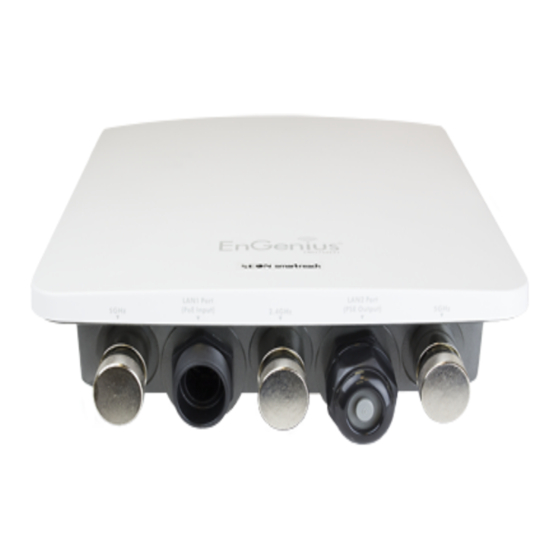
Antenna Connectors
The image shows a top view of the access point.
Connectors labeled 1, 3, and 5 are for 2.4 GHz antennas,
0
while 2, 4, and 6 are 5 GHz.
Smart-Reach AC Base Installation
Follow the procedures in the included Quick Installation
Guide and the supplied installation accessories to secure
the Smart-Reach AC Base access point to the location
identified by Seon engineering professional services.
Ensure power, LAN, and antenna status lights are visible
from the selected mounting location.
1
Advertisement
Table of Contents

Summary of Contents for SEON Smart-Reach 032-1025
- Page 1 Follow the procedures in the included Quick Installation Guide and the supplied installation accessories to secure the Smart-Reach AC Base access point to the location identified by Seon engineering professional services. Ensure power, LAN, and antenna status lights are visible from the selected mounting location.
- Page 2 Smart-Reach AC Base–Antenna Connection Guide Antenna Installation Ensure each antenna and its cabling is installed using the installation instructions provided with the antenna. Antennas should be located five to ten feet above the roof level of the buses. A lightning arrestor is integrated at each antenna port.
- Page 3 If the connectors are uncovered, moisture will enter and damage the Smart-Reach AC Base. This SRB1AC101010 will void the Seon product warranty. Remove caps from antenna connector numbers 1, 3, and 5. Antenna Types Securely attach cable connectors for the three 2.4 GHz Omni antennas to the three connectors.
Need help?
Do you have a question about the Smart-Reach 032-1025 and is the answer not in the manual?
Questions and answers