Table of Contents
Advertisement
Advertisement
Table of Contents

Related Manuals for Lencore GOLD A1U

Summary of Contents for Lencore GOLD A1U
- Page 1 GOLD ™ DESIGN, INSTALLATION AND OPERATION GUIDELINES (Model A1U)
-
Page 2: Table Of Contents
table of contents INTRODUCTION Diagram Wiring Connections Configuring the System Flow Diagram System Zoning Speaker Layout Installation IR Wall Controls Tuning and Balancing Changing the IP Address Operating the System from the Front Panel... - Page 3 IMPORTANT SAFETY INSTRUCTIONS RISK OF ELECTRIC SHOCK- DO NOT OPEN THE UNIT. THERE ARE NO SERVICABLE COMPONENTS INSIDE. Read these instructions. Keep these instructions. Heed all warnings. Follow all instructions. Do not use this apparatus near water. Clean only with dry cloth. Do not block any ventilation openings.
-
Page 4: Introduction
The following pages include design, installation and operation guidelines utilized to reach the best possible performance from the Lencore sound masking system. The goal of a sound masking system is to provide speech privacy by raising the ambient background noise with a comfortable sound that is uniform throughout the space. -
Page 5: Diagram
Sound Masking Speakers The Gold system utilizes either 4" direct-fired or 6" in-plenum speakers. Direct-fired speakers are either mounted in the ceiling (Gold Direct Fired Tangent) or attached to the ceiling / deck (Gold Decorative Pendant) and face downward for direct, unimpeded delivery of the sound. - Page 6 See “Using the System” for detailed information. 7. IR Inputs Connect the IR input to a Lencore’s IR 3. Buttons device using an RJ45 cable for OP1 and OP2. The switches are used to make a number of adjustments to the system without using a 8.
-
Page 7: Wiring
2. Connect a network cable to the unit’s Ethernet input to access the Protocessor. The Protocessor is the network server. The Protocessor is pre-loaded with Lencore’s System Manager. System Manager allows adjustment to the system’s characteristics. Note: The network cable must be a standard Ethernet cable not power over Ethernet (POE). - Page 8 IR connections: 1. Connect an IR unit to the IR port. IR1 for OP1 speakers. IR2 for OP2 speakers. IR 1 IR 2 Speaker connections: 1. Connect the external speakers to the appropriate channel using cat 5 RJ45 cables. CH 1A CH 1B CH 1C CH 1D...
-
Page 9: Configuring The System
Auxiliary Connection Connect an external device’s fault input to Aux “Fault Out” Relay R1 - NC and C. Relay R1 is energized (closed) when no fault exists and de-energized (open) when a fault is active. Input 1A and 1B are for future use. Input 2A and 2B are for future use. -
Page 10: Flow Diagram
Flow Diagram Back View *Diagram above is for wiring purposes only and is not an exact representation of the actual unit Gold utilizes both direct fired (Gold Direct Fired Tangent and Gold Decorative Pendant) and indirect firing (Gold Universal In-Plenum) speakers. Based on the space and the layout, each channel can accommodate up to 8 speakers per channel. -
Page 11: System Zoning
System Zoning Note: Lencore provides design layout at no cost. Speaker placement, zones and channel assignments are all complimentary as part of the Lencore design process. Contact Lencore today at 516-682.9292. Zoning is determined by the function of the space being served by sound masking as well as ceiling height. For example, separate zones are used for open offices, private offices, and corridors due to their requirement for differing sound masking volumes. -
Page 12: Speaker Layout
Speaker spacing is based on ceiling / mounting height. Lencore speakers have the same minimum and maximum spacing requirements from acoustic boundaries such as walls or columns. If a device is too close or too far away from a boundary, a change in sound level may be discernible by occupants and should be avoided. - Page 13 In many cases it will be necessary to adjust the last row or last several rows of speakers to compensate for room dimensions. In these cases, it is important to lessen the distance between speakers to maintain adequate coverage rather than increasing it.
- Page 14 < 144 square feet Less than 1 Hour Above 14’ Call Lencore Less than 1 Hour In cases where the time duration of exposure, the room size is exceeded in reference to ceiling height, or the speaker location is offset due to ceiling conflicts, refer to Table 3 above for multiple speaker placement.
-
Page 15: Installation
Failure to leave a 1RU of empty space above the unit can result in the unit overheating and eventual failure. Rubber feet are available to place the unit on a shelf or desk if a rack is not available. Contact Lencore for more information at 516-682-9292 or info@lencore.com. WALL MOUNTED 1. Unscrew bracket from headend unit. - Page 16 Use of the Tile Bridge improves environmental safety and eliminates unsightly sag in 2’-by-2’ and 2’-by-4’ acoustic ceiling tiles. Please comply with all applicable building codes for installation. Lencore does not take responsibility for installation of speakers, wiring or equipment.
- Page 17 INSTALLATION DIAGRAMS Side Bottom...
- Page 18 INSTALLATION DIAGRAMS *Tile Bridge (TB4) Not Shown For additional Technical Support call: 516-682-9292...
- Page 19 INSTALLATION INSTRUCTIONS FOR GOLD DECORATIVE PENDANT SPEAKERS For additional support, please see our speaker installation videos on the Lencore website at: www.lencore.com Refer to the sound masking layout (drawing) provided to locate the appropriate speaker installation position. Secure speaker mounting plate to ceiling octagon...
- Page 20 Gold Decorative Pendant Speaker installation diagram 4" x 1.5"...
- Page 21 INSTALLATION INSTRUCTIONS FOR THE GOLD IN-PLENUM UNIVERSAL SPEAKER For additional support, please see our speaker installation videos on the Lencore website at: www.lencore.com 1. Access the ceiling plenum. 2. Orient speaker to face the speaker grill upwards or downwards based on project design and affix enclosed tripod chain to lances on either end.
- Page 22 INSTALLATION DIAGRAMS...
-
Page 23: Ir Wall Controls
Optional Infrared (IR) Wall Controls Gold is equipped with two (2) integrated infrared eye ports, one for each OP. This allows for either a wall keypad or remote control with a wall IR Eye (both sold separately) to be used to adjust the system. Adjustments to the system may be made for the masking volume or the audio channel. - Page 24 IR TOUCH PAD CONTROLLER CONFIGURATION Fr ont of W al l Pl ate The IR Touch Pad Controller comes with all dip switches in the down position by default. This default setting will allow the IR Touch pad controller to be used with the IR Hub model G482 out of the box.
- Page 25 IR TOUCH PAD CONTROLLER CONFIGURATION MANUAL The IR Touch pad, without a Hub, can be configured to control a single channel or all 4 channels not a combination of channels. Hub Position - Use this position when using an IR Hub - All DOWN Channel A Only - No Hub, Direct to OP-IR Port...
-
Page 26: Tuning And Balancing
Quick Start Guide: System Manager System Manager is Lencore’s graphic user interface that allows sound masking system adjustments to be made via a PC in a simple, easy manner. System Manager interfaces with Gold via the Ethernet Connection port on the back of the unit. - Page 27 The computer must be configured properly with an IP Address that is different from the device. Follow this sequence: Access Network Settings Change Adapter Settings...
- Page 28 Right click on your Ethernet connection Click Properties Right Click then Click "Properties" Highlight “Internet Protocol Version 4 (TCP/IPv4)” and click Properties...
- Page 29 Click “Use the following IP Address” radial button and type in the following: 192.168.100.200 It should look like the following: Click “OK” and exit out of set-up.
- Page 30 Access any Internet browser (Chrome, Safari, Internet Explorer, etc.) on your computer. In the URL address box type: 192.168.100.225. NOTE: This ID number is different from the set-up ID number. The System Manager Login Screen should appear: The login default settings are: Username: comfort Password: comfort After logging in you will be presented with five tabbed options to select from:...
- Page 31 Clicking on an OP will bring up the Controls and Tabs for that OP.
- Page 32 You are able to adjust the masking volume and contour by moving the slider itself up and down, clicking the “Up”, “Down”, and “Mute” buttons or by clicking on the value and keystroking in a new number. Each channel is adjusted independently. Typically your final decibel level will be arrived at by adjusting both the masking attenuation (volume) and contour (frequency) controls.
- Page 33 Zone Tab Zones are groups of OP channels. They allow you to combine and control multiple channels at the same time. The Zone tab, when first selected, presents you with a sub-menu of tabs for each type of zone available: Masking or Audio. Selecting either of these tabs will present a list consisting of all of the zones that have been added to the system for the selected zone type as well as a button for adding a new zone of the selected type. Each individual Zone item consists of the following information: • Grey “Zn” Icon • Zone # and Friendly Name. Friendly name is assignable once the Zone has been selected and will be blank if no Friendly Name has been assigned. Selecting one of the Zones will bring you to the Zone Editing screen which will allow you to adjust several attributes of the zone.
- Page 34 The Zone Tab defaults to the Audio Setup where you can adjust the volume and the contour for sound masking (you can adjust the volume for the audio when in the Audio tab.) Use the sliders, the Up, Down and Mute buttons, or, highlight the values themselves and type in a value to adjust the volume and contour.
- Page 35 NOTE: In most instances, the equalizer should not be adjusted unless there is a specific curve you want to apply. Lencore sets the masking at a comfortable curve out of the box. You have the flexibility to delete zones by clicking on the Delete This Zone link.
-
Page 36: Changing The Ip Address
PC to the "Protocessor Field Pop Enabled" port on the back of the Headend. (See Interfacing with the protonode section of the manual for further instructions). 2. Open a web browser and enter the Headend IP address. 3. On the Lencore landing page, select the "Systems Setting" option. - Page 37 Your set-up is now complete. Enjoy your Gold System and the best sound masking in the market. If you have any questions or need assistance our team of Technical Support Experts and Customer Service Managers are always here to assist you: 516-682-9292 or support@lencore.com...
-
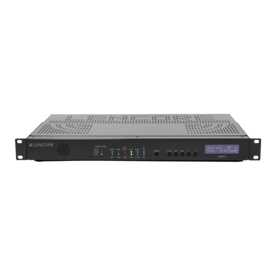
Page 38: Operating The System From The Front Panel
OPERATING THE SYSTEM FROM THE FRONT PANEL Front Panel Buttons: The buttons allow the user to make a number of adjustments to the system without using a computer, although, a computer and System Manager are still required for full control of all functions (see previous section to access the Network and login to System Manager). - Page 39 Options and Functions: Function Option Select Function Option Select Channel Masking Channel Volume Music Volume Mute Zone Mute Zone Volume Mute IP Address View Only Channel Masking Subnet View Only Contour Contour Info Gateway View Only Zone MAC ID View Only Contour Select Volume...
- Page 40 Masking Mute: Press the FUNC button until “Mask Muter” is displayed. OP/Channel: Press the OPT button until “OP” is displayed. Press the SEL button until the curser is on the value to change (OP number, channel letter, or volume). Both OP's (OP ALL) or individual OP's (OP1 or OP2) or individual channels (A,B,C,D) can be selected.
- Page 41 Front Panel Indicators Neuron activity The Neuron is a specialized internal microprocessor. The LEDs labeled TX and RX indicate Neuron activity. These LEDs will be flickering under normal operation. The FLT LEDs are indicators for system faults. The CPU LED indicates that the internal CPU (microprocessor) is in a fault condition.
- Page 42 Inputs The INPUTS LEDs are indicators for system inputs. FTR1 represents the Mute masking input. FTR1 FTR2 Relays Relay RL1 LED indicates a general fault. When the LED is on, no fault exists and Relay RL1 is energized. When the LED is off, a fault has occurred and Relay RL1 is de-energized. AUX LED is for future use.
- Page 43 Woodbury, NY 11797 516-682-9292 info@lencore.com www.lencore.com The information contained herein is proprietary to Lencore Acoustics LLC and copyright protected. No part of this manual can © be copied, used or distributed without prior authorization from Lencore Acoustics Corp. Copyright 2020...
Need help?
Do you have a question about the GOLD A1U and is the answer not in the manual?
Questions and answers