Advertisement
Quick Links
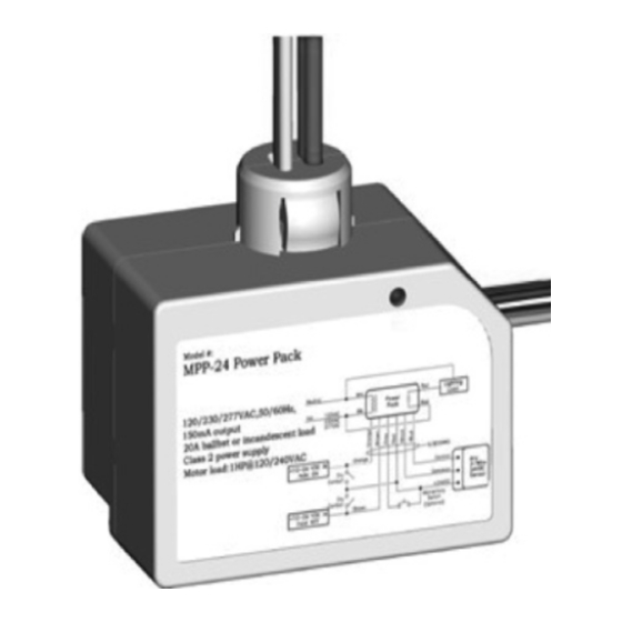
MODEL: IOS-PP24
INSTALLATION AND CONFIGURATION INSTRUCTIONS
Specifications:
Input Voltage: 120/230/240/277 VAC 50/60 Hz
Load Requirements
Ballast - 20 A @ 120/240/277 VAC
Electronic Ballast/LED: 500 W
Tungsten/Incandescent: 15 A, 120 VAC 50/60 Hz, 5 A, 250 VAC 50/60 Hz
Motor: 1 HP 120/240 VAC 50/60 Hz
Output - 150mA @ 24 VDC Class 2 Power Supply (with relay connected)
Low Voltage Input
Control ON - 12-24 VDC
Hold ON - 12-24 VDC
Hold OFF - 12-24 VDC
Manual ON (momentary switch required) - 12-24 VDC
DESCRIPTION:
The IOS-PP24 Power Pack supplies low voltage lighting control system. The power pack supplies low
voltage power to occupancy sensors and other control devices, switching line voltage in response to
signals from control devices.
INSTALLATION GUIDELINES
Follow these guidelines before beginning installation of the power pack:
• Install power packs in accordance with state, local, and national electrical codes and requirements
• Power packs attach to existing or new electrical enclosures with ½ inch knockouts.
• Most applications require UL listed, 18-22 AWG, 3 conductor, Class 2 cable for low voltage wiring.
For plenum return ceilings, use UL listed plenum approved cables
• The IOS-PP24 is a Class 2 Output Power Supply, suitable for parallel interconnection of up to 6 units
maximum.
• The power pack is UL listed for interconnection of power sources in accordance with National
Electrical Code
MOUNTING THE POWER PACK
NOTE: After the wire connections are made, verify the wire installation was completed properly.
Improper wiring can cause damage to the power pack, lighting system, occupancy sensor, and other
control devices.
NOTE: A customer-supplied junction box is needed to complete this procedure.
1. Make sure power is turned off at the circuit breaker.
2. Punch loose a knockout on the customer-supplied junction box.
3. Insert the power pack nipple into the opening in the junction box knockout.
4. Connect the power pack input wires as shown in Figure 2.
NOTE: The occupancy sensor contains four +12 to 24 VDC input wires to control the load relay. The
inputs may be used in combination or individually depending on the needs of the application. See
the table below for a description of the inputs.
Input (wire)
Control ON (Blue wire)
Hold ON (Orange)
Hold Off (Brown)
Manual ON/OFF (Gray)
5. Refer to Figure 2 to verify the power pack is wired correctly.
OPERATION
The occupancy sensor enables the load to be automatically turned ON/OFF with an occupancy sensor
input, timer, panel, or BAS input. The load can also be manually turned off from an optional low voltage
momentary switch.
OVERRIDING THE POWER PACK WITH MOMENTARY SWITCH (OPTIONAL)
The Power Pack can be overridden from the connected momentary switch. The momentary switch
can override the Power Pack when it is in the Control ON, Hold ON, and Hold OFF states.
OVER CURRENT PROTECTION
The IOS-PP24 Power Pack contains built-in short circuit and thermal protection circuitry that shuts
down the +24 VDC output (low voltage red wire) when the output exceeds 200MA to prevent permanent
damage to the power pack. Removing the excess load from the output restores the occupancy sensor to
proper operation.
• Turn OFF power at circuit breaker or fuse and test that the power is OFF before wiring.
• To be installed and/or used in accordance with appropriate electrical codes and regulations.
• If you are not sure about any part of these instructions, consult a qualified electrician.
• Use this device only with copper or copper clad wire.
•
Description
Occupancy sensor input. Applying 12 to 24 VDC
closes the relay.
Time or panel input. Applying 12 to 24 VDC closes
the relay.
Timer, panel, BAS, or load shed input. Applying
12-24 VEDIC opens the replay.
Low voltage momentary switch, if applicable.
IOS-PP24
WARNING
Risk of Fire, Electrical Shock or Personal Injury
INDOOR USE ONLY
Neut.
120VAC Black
Hot
277VAC
+12-24VDC In
Hold On
+12-24VDC In
Hold Off
Neutral
Hot
Notes:
1. Relay shall be assigned to
a Schedule to keep Motion
Sensors from turning lights
off during "Occupied" hours.
Relay on "Holds" lights on.
Relay off allows full Sensor
control of the lights.
2. IOS-PP24 Power Packs
have150ma 24VDC
available for Motion Sensors.
12-24 Volt
Power Pack
High
Voltage
Figure 1
Lighting
White
Power Pack
Red
Load
Red
Low Voltage Wires
Orange
Control
Any 3-Wire
Common
24VDC
+24VDC
Sensor
Brown
Momentary Switch (optional)
Figure 2
3-wire Push Button
Low Voltage
2-wire Push Button
Gray
Momentary
Manual ON
Gray
Install
Red
Switch Option
Manual ON
Jumper
24VDC
Wire
Wiring
Red
24VDC
Figure 3
White/Neutral
2
Red
Wht
IOS-PP24
Blk
Power
Red
Pack
Power Pack hold on with Relay
Cap
Cap
om ("Hold On" Power)
Red +24VDC
Control
Output
Common
+24VDC
Only the wires used in
this application are shown.
Control
Output
Common
+24VDC
Control
Output
Common
+24VDC
To other motion
Sensor as
( Lights are held on during day by Scheduled Relay )
Needed 2
Figure 4
Low
Voltage
Multi-button Switch
Do not use pilot or locator
light connections
Gray
S(x)
Manual ON
Red
Com
24VDC
Located in
Relay Panel
RELAY 1
Occupancy
Sensor
IOS-CMP-LV
Occupancy
Sensor
IOS-CMP-LV
Occupancy
Sensor
IOS-CMP-LV
Advertisement

Related Manuals for Intermatic IOS-PP24


Summary of Contents for Intermatic IOS-PP24
- Page 1 White Power Pack Load Neut. • The IOS-PP24 is a Class 2 Output Power Supply, suitable for parallel interconnection of up to 6 units 120VAC Black maximum. 277VAC • The power pack is UL listed for interconnection of power sources in accordance with National...
- Page 2 LIMITED WARRANTY Warranty service is available by either (a) returning the product to the dealer from whom the unit was purchased or (b) completing a warranty claim online at www.intermatic.com. This warranty is made by: Intermatic Incorporated, 1950 Innovation Way, Suite 300, Libertyville, IL 60048. For additional product or warranty information go to: http://www.Intermatic.com or call 815-675-7000.
Need help?
Do you have a question about the IOS-PP24 and is the answer not in the manual?
Questions and answers