
Summary of Contents for EPS Ecraft Pro Series
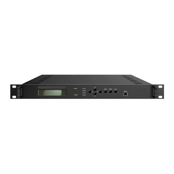
- Page 1 EPS-HDM1004ECO 4 HDMI input Encoder Modulator ELECTROCRAFT AUSTRALIA 36 Binney Road, Marayong NSW 2148 T: (02) 8811 5155 F: (02) 9831 2139 www.electrocraft.com.au...
-
Page 2: Chapter 1 Introduction
Chapter 1 Introduction 1.1 Product Overview EPS-HDM1004ECO encoder modulator is all-in-one device integrating MPEG2 encoding and modulating to convert audio/video signals into DVB-T RF out. It support 4 HDMI inputs. The signal source could be from STB, satellite receiver, closed-circuit television cameras and antenna etc. Its output signal is to be received by TVs or STBs etc. -
Page 3: Specifications
1.3 Specifications RF frequency 100-1000MHz, 1KHz step HDMI Encoding Section RF output level -48~ -10dBm, 1dB step Input Interface HDMI*4 ISDB Modulator Section Encoding MPEG2 Input Output Standard ARIB STD-B31 Constellation QPSK, 16QAM, 64QAM 480@59.94/60i 480@30p Guard Interval 1/32, 1/16, 1/8, 1/4 576@50i 576@25p Transmission... -
Page 4: Appearance And Description
1.4 Inner Principle Chart Encoding Encoding Modulating Carrier 1# HDMI 1# MPEG2 HD/SD DVB-C/T/ATSC/ISDBT/DTMB Carrier 2# HDMI 2# DVB-C/T/ATSC/ISDBT/DTMB MPEG2 HD/SD Carrier 3# HDMI 3# MPEG2 HD/SD DVB-C/T/ATSC/ISDBT/DTMB Carrier 4# HDMI 4# MPEG2 HD/SD DVB-C/T/ATSC/ISDBT/DTMB Carrier 5# HDMI 5# MPEG2 HD/SD DVB-C/T/ATSC/ISDBT/DTMB Carrier 6# HDMI 6#... - Page 5 Rear Panel Illustration RF output 4 HDMI input and 4 CC input ports Power Switch/Fuse/Power socket Grounding Pole...
-
Page 6: Chapter 2 Installation Guide
Chapter 2 Installation Guide This section is to explain the cautions the users must know in some case that possibly injure may bring to users when it’s used or installed. For this reason, please read all details here and make in mind before installing or using the product. 2.1 General Precautions ... -
Page 7: Environment Requirement
2.4 Environment Requirement Item Requirement When user installs machine frame array in one machine hall, Machine Hall the distance between 2 rows of machine frames should be Space 1.2~1.5m and the distance against wall should be no less than 0.8m. Electric Isolation, Dust Free Volume resistivity... -
Page 8: Chapter 3 Operation
25 mm Chapter 3 Operation EPS-HDM1004ECO encoder modulator’s front panel is user operating interface. Before operating, user can decide whether directly use the default setting or customize the input and output parameters setting. The detail operations go as follows:... -
Page 9: Lcd Menus
3.1 LCD Menus An overview of the LCD menus:... -
Page 11: General Settings
3.2 General Settings By pressing LOCK key, users can enter in the main menu and set the parameters in the following editing interfaces, the LCD will display the following pages: ►1 Status 2 TS Config 3 Encode 4 Modulate 5 Network 6 System Setting 7 Soft Version The option with “►”... - Page 12 2.8 Channel 8 Channel 1/2/3/4 EPS-HDM1004ECO supports 4 Channels output with DVB-T modulating. Users select different modulating modes for each channel under the menu of “3.2.4 Modulate”, the TS parameters will be different, LCD will display the following pages: Selecting modulation mode as DVB-C: 3.2.3 Encode...
- Page 13 PMT PID Video PID 3.2.4 Modulate EPS-HDM1004ECO supports 4 RF out carriers, users can enter the corresponding channels to select modulation mode and set the relevant RF output parameters. ►4.1 Channel 1 4.2 Channel 2 4.7 Channel 7 4.8 Channel 8...
-
Page 14: Factory Set
3.2.5 Network Setting After enter Network Setting, there are four submenus shows as the following LCD displays. IP Address 192.168.000.136 Subnet Mask 255.255.255.000 Gateway 192.168.000.001 MAC Address xx:xx:xx:xx:xx:xx 3.2.6 System setting Save Users can enter Saving Configuration submenu for saving settings. Choose yes and press ENTER to confirm. -
Page 15: Chapter 4 Web Nms Operation
User not only can use front buttons to set configuration, but also can control and set the configuration in computer by connecting the device to web NMS Port. User should ensure that the computer’s IP address is different from the EPS-HDM1004ECO IP address; otherwise, it would cause IP conflict. - Page 16 4.2 Operation When we confirm the login, it displays the WELCOME interface as Figure-2. Click here to check the version information User can click any item here to Click here to check the enter corresponding encode and modulate interface to check information version information or set the parameters.
- Page 17 Under the modulation type of DVB-T Under the modulation type of ATSC...
- Page 18 Under the modulation type of DTMB Under the modulation type of ISDB-T Figure-3 Parameters → → → → Encode: Clicking “Encode”, it displays the information of the program from the 8 HDMI encoding channels as Figure-4.
- Page 19 8 encoding channels Audio encoding format: MPEG1 Layer2, MPEG2-AAC, AC3 Figure-4 Parameters → → → → Modulate: Clicking “Modulate”, it displays the interface where users can configure the modulating parameters. Clicking “Setting Type→PART SET” to select modulation type and set frequency for each channel (Figure-5);...
- Page 20 Select modulation type: DVB-C DVB-T, ATSC-T, DTMB, ISDB-T. Figure-6 Clicking “Channel1/2/3/4”, it displays the interface where users can configure the modulation parameters (Figure-7). Each channel supports 1 DVB-T output option. Here we select DVB-T modulation types for Channel 1-5 as an example. DVB-T modulating...
- Page 21 System → → → → Network: Clicking “Network”, it displays the interface as Figure-7 where to set network parameters. Figure-7 System → → → → Password: Clicking “Password”, it displays the screen as Figure-8 where to set login account and password for the web NMS.
- Page 22 Figure-9 System → → → → Save/Restore/Factory Set/Backup/Load: Clicking “Save/Restore/Factory Set/Backup/Load”, it displays the screen as Figure-10 where to Save/Restore/Factory Set/Backup/Load your configurations.
Need help?
Do you have a question about the Ecraft Pro Series and is the answer not in the manual?
Questions and answers