Advertisement
PROGRAMMING (Cont'd)
Mutually Exclusive Control:
Button B1~B3 or Button B1~B4 maybe grouped for mutually exclusive control. Only one of the buttons may be turned ON at a time.
1. Press and hold
B1
and
B4
for 3 seconds to enter PROGRAMMING MODE.
Top Left LED Indicator x4 will light to indicate that you are in PROGRAMMING MODE.
2. While in PROGRAMMING MODE, press Button B1 or B2 for 3 seconds to turn ON/OFF its green backlit.
Green Backlit
Mutually Exclusive Group
Button B1 ON
Button B1~B3
Button B2 ON
Button B1~B4
Button B1&B2 OFF
Independent Controlled (default)
3. Once set, press and hold
B1
and
B4
for 3 seconds to exit PROGRAMMING MODE.
Note:
While in mutually exclusive group, Button B2 will active all SW1, SW2 & SW3 connection together.
When configuring as Mutually Exclusive Group, these buttons must be configured as "ON/OFF switch".
European Siren Interlock:
The Button B5 and B6 may be configured so that Button B5 turns Button B6 OFF when deactivated and turn itself ON when Button
B6 is activated. This configuration is commonly used for that Button B5 is used as the primary visual warning device and Button B6
is use as a siren activation.
1. Press and hold
B1
and
B4
for 3 seconds to enter PROGRAMMING MODE.
Top Left LED Indicator x4 will light to indicate that you are in PROGRAMMING MODE.
2. While in PROGRAMMING MODE, press Button B6 for 3 seconds to turn ON/OFF the green backlit.
Button B6 Green Backlit
Mode
OFF
Interlock OFF (default)
ON
Interlock ON
3. Once set, press and hold
B1
and
B4
for 3 seconds to exit PROGRAMMING MODE.
Note:
When configuring as Button mapping mode, Button B5 and Button B6 must be configured as "ON/OFF switch".
Button Mapping:
Button B7 may be set to activate and deactivate by Button B5.
1. Press and hold
B1
and
B4
for 3 seconds to enter PROGRAMMING MODE.
Top Left LED Indicator x4 will light to indicate that you are in PROGRAMMING MODE.
2. While in PROGRAMMING MODE, press Button B5 for 3 seconds to turn ON/OFF the green backlit.
Button B5 Green Backlit
Mode
OFF
No Button Mapping (default)
ON
Button B7 Mapped with Button B5
3. Once set, press and hold
B1
and
B4
for 3 second to exit PROGRAMMING MODE.
Note:
When configuring as Button mapping mode, Button B5 and Button B7 must be configured as an "ON/OFF Switch".
LED Signal Display Mode Change:
The 10-LED Signal Display may display either the Lightbar flash signal or the
the display mode:
1. Press and hold
B1
and
B4
for 3 seconds to enter PROGRAMMING MODE.
Top Left LED Indicator x4 will light to indicate that you are in PROGRAMMING MODE.
2. While in PROGRAMMING MODE, press Button B8 to turn ON/OFF the red backlit.
Button B8 Red Backlit
Mode
Directional / warning advisor
OFF
flash signal (default)
ON
Lightbar flash signal
3. Once set, press and hold
B1
and
B4
for 3 seconds to exit PROGRAMMING MODE.
Application Example
Application Example
Application Example
directional / warning advisor
flash signal. To change
- 4 -
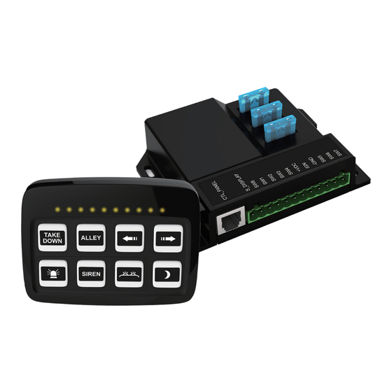
SW830
Multi-purpose Switch / Control
Panel w/ Power Module
INSTALLATION
It is essential to install the unit properly to ensure safe and reliable operation. Please read through all instructions thoroughly and
carefully before installing the unit. The correct mounting and wiring is the key to the effectiveness of SW830 switch. Installers must
read and follow installation instructions and warnings in the manual from original manufacturer. The vehicle operator should verify this
system is fastened to the vehicle securely and is functioning properly. Failure to follow all safety precautions and instructions may void
warranties, cause personal injury and/or vehicle damage, including fire.
MOUNTING
Mount the power module in a location that is not exposed directly to weather elements such as the driver compartment firewall, below
the seat, or in the trunk; and away from any air bag deployment areas. Ensure that all wiring harness connections are made prior to
connecting the harness to the power module.
Assemble the included panel stand and secure it onto a desired smooth surface via suction cup, where it can be easily accessed by
the vehicle operator. If no smooth surface is present, use the included adhesive base to assist the mounting; ensure that the surface
is cleaned thoroughly before applying the adhesive base onto the mounting surface. Leave adhesive to set for at least 24hr before
mounting the suction cup on to the base. Once the mounting stand is fitted, secure the control panel tightly onto the stand.
WARNING:
Do not interfere with the proper operation of the vehicle airbag deployment system.
Note:
Avoid mounting the switch unit with wiring harness exiting downward. This may cause harness connection to fall off during
harsh or sudden impact.
Power Module
Control Panel
- 1 -
171226A03
Advertisement
Table of Contents

Summary of Contents for Zone SW830
- Page 1 It is essential to install the unit properly to ensure safe and reliable operation. Please read through all instructions thoroughly and carefully before installing the unit. The correct mounting and wiring is the key to the effectiveness of SW830 switch. Installers must read and follow installation instructions and warnings in the manual from original manufacturer.
- Page 2 WIRING CONTROL PANEL / FUNCTION Use wires that are capable of handling the required current. Route the wires properly to prevent wear, overheating and interference To turn on the control panel, apply positive voltage to the IGN (Ignition) terminal at the rear of the power module. with air bag deployment.
Need help?
Do you have a question about the SW830 and is the answer not in the manual?
Questions and answers