Table of Contents
Advertisement
Quick Links
Proteus User Manual
V2.0 October 2020
Proteus Instruments Ltd, Leask House, Hanbury Road, Stoke Prior, Bromsgrove, B60 4JZ, United Kingdom
© 2020 Proteus Instruments Ltd. E & O E. All rights reserved.
www.proteus-instruments.com | info@proteus-instruments.com | +44 1527 433221
Patented GB2553218 | Version 2.0
Advertisement
Table of Contents
Troubleshooting

Related Manuals for Proteus Proteus

Summary of Contents for Proteus Proteus
- Page 1 Proteus User Manual V2.0 October 2020 Proteus Instruments Ltd, Leask House, Hanbury Road, Stoke Prior, Bromsgrove, B60 4JZ, United Kingdom © 2020 Proteus Instruments Ltd. E & O E. All rights reserved. www.proteus-instruments.com | info@proteus-instruments.com | +44 1527 433221 Patented GB2553218 | Version 2.0...
- Page 2 Any suggestions that would help improve the clarity of the information presented in this manual or additional information that would enhance understanding and operation is welcomed. Proteus Instruments is committed to the improvement of its products and services therefore reserve the right to change instructions, specifications and schematics without notice.
- Page 3 Each fluorometer houses an ultra-violet LED. DO NOT LOOK DIRECTLY AT THE LED WHEN THE PROTEUS IS CONNECTED TO POWER. Exposure to UV light can cause damage to eyes. When looking at the optical window, use appropriate safety googles.
-
Page 4: Table Of Contents
2.2.2 Unattended Logging............................6 2.2.3 Telemetry................................6 2.2.4 Online, Real-time Monitoring..........................6 2.3 STATUS INDICATOR LIGHTS..............................7 2.4 ACCESSORIES..................................8 2.4.1 Proteus High Range Dilution Sampling System..................8 2.4.2 Remote Telemetry Systems .........................8 3. COMMUNICATION SOFTWARE............................9 3.1 SYSTEM REQUIREMENTS..............................9 3.1.1 Control Software and Serial Adaptors......................9 3.1.2 Trouble Shooting...............................9 3.2 INTERFACE SCREEN................................10... - Page 5 6.9 SITE-SPECIFIC CALIBRATION............................28 6.10 CALIBRATION OF OTHER SENSORS.........................29 6.10.1 Setting Time, Date and Barometric Pressure (BP)................30 6.10.2 Dissolved Oxygen (HDO)..........................31 6.10.3 Electrical Conductivity/Specific Conductance..................32 6.10.4 pH..................................32 6.10.5 Oxidation-Reduction Potential (ORP) ....................32 6.10.6 Depth and Vented Depth (Gauge)........................33 6.10.7 Ion Selective Electrodes (ISEs)........................33 6.10.8 Total Dissolved Gas (TDG)........................34 6.10.9 PAR..................................34 7.
- Page 6 Figure 5: Optional Proteus Transport case. Figure 6: Direct comparison of Proteus with IBP (foreground) and Proteus without IBP (Background). Figure 7: An example of a Proteus set-up using solar power and transmitting data via to the outpost cloud server.
-
Page 7: Background
As such, it is considered the best indicator of faecal pollution and by extension, the presence of pathogens. For a comprehensive list of all the parameters that can be measured by the Proteus, please refer to the product datasheet. -
Page 8: What Is Fluorescence
1.1 What is Fluorescence? Fluorescence is a form of luminescence (i.e. the emission of light not attributed to thermal radiation) that occurs over very short time scales (10-9 – 10-7s). The first fluorescent substance to be observed and recorded was quinine sulphate (a key ingredient in tonic water). In Figure 1 we can see fluorescence in action –the quinine sulphate molecules absorb ultra-violet light (short wave radiation) from the laser pen and then emit blue light (longer wavelength radiation). -
Page 9: Measuring Organic Matter Using Fluorescence
1.2 Measuring Organic matter using Fluorescence A significant proportion of Chromophoric (light absorbing/coloured) organic matter is fluorescent when excited by light in the UV region. Using laboratory fluorometers that scan the full spectrum of excitation and emission wavelengths (Excitation Emission Matrix spectroscopy; EEM), distinct fluorescent peaks have been identified (Fig. -
Page 10: Instrument Specifications
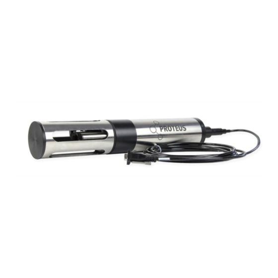
2. Instrument Specifications 2.1 Instrument Figure 4: Typical Proteus Equipment Overview; please note: this varies depending on individual requirements. Table 1: Key for Figure 4 1. Sensor Guard 6. Proteus Control Software 2. Sensor Array 7. Comms Cable 3. Proteus Body/Housing 8. -
Page 11: Figure 6: Direct Comparison Of Proteus With Ibp (Foreground) And Proteus Without Ibp (Background)
≥1Hz Internal Memory 4MB; >1,000,000 readings Warranty 24 months (options to extend) *depending on specification purchased If you require individual sensor specifications, please contact us directly. Figure 6: Direct comparison of Proteus with IBP (foreground) and Proteus without IBP (Background). -
Page 12: Applications And User Modes
Amphibian2 display (purchased separately). Real-time data to a laptop will be displayed on the Proteus software and can be ‘snapshotted’ at user defined intervals to a csv file. The Proteus data can also be accessed using a compatible Bluetooth enabled tablet and/or smartphone; this requires an additional purchase of the Bluetooth battery module. -
Page 13: Status Indicator Lights
2.3 Status Indicator Lights The Proteus and the external SDI-12 adaptor (see section 6.5) have three light-emitting diodes (LEDs) mounted on the circuit board top. They are visible from the outside through the transparent housing of the SDI 12 converter and on the top of the sensor housing in the stainless model. -
Page 14: Accessories
Our flow cells are cut to size depending on your requirements; please get in touch with us for more details. 2.4.2 Remote Telemetry Systems For remote applications, Proteus Instruments has designed a range of telemetry options to suit a variety of equipment set-ups. The telemetry relay can be housed in a custom-built Pelicase (Figure 6) or outstation. -
Page 15: Communication Software
Once the Proteus is plugged in via the adapter to your PC, start the control software. If you have a highly specified Proteus or with a long cable length (>30m) you may need the auxiliary power supply that connects into the USB adaptor. -
Page 16: Interface Screen
Figure 9: Proteus control software interface screen. 3.3 Hot Buttons Figure 10: Overview of Proteus Control software hot buttons. Please note, the numbers are for guidance only and do not appear on the actual interface. Informs the Proteus that logging mode is enabled/disabled. To activate unattended logging, the switch plate on the Proteus must also be moved into the ‘on’... -
Page 17: Drop Down Menus
3 .4 Drop Down Menus The Proteus software has two Drop-Down Menus; ‘PC’ and ‘Proteus’ . Within these two menus all the software settings and calibration tools can be accessed. 3.4.1 PC Menu Used to change the time interval for the lines of data displayed on the software screen The ‘Snapshot’... -
Page 18: Custom Parameters
For more information, please refer to the separate RS232 manual which is available on request. Opens separate menu of parameters for calibration. This list includes every possible parameter a Proteus can have, but you can only calibrate for parameters where you have the corresponding sensor. For more information on calibration procedure, see Section 6. -
Page 19: Figure 14: Custom Parameter Creation Dialogue Box
Proteus, then waiting 10 seconds before reconnection. Due to the versatility of the Proteus, it is possible to use the Proteus for a range of applications spanning a variety of water environments (natural – engineered). In this section, installation recommendations are outlined for the two most commonly encountered applications. -
Page 20: Installation
An alternative installation option involves non submersible deployment, usually associated with a peristaltic pump through or process applications. If this is desirable attach the flow-cell (Figure 17) to the Proteus in place of the sensor guard and attach the feed line to the barbed connectors. -
Page 21: Maintenance
The sensor guard can be removed for cleaning but be careful with the sensors when handling the Proteus without the guard in-place. DO NOT LOOK DIRECTLY AT THE LED WHILE THE PROTEUS IS ON. 5.1 Routine Maintenance and Cleaning To ensure accurate and reliable data during longer term installations, regular cleaning of the multiprobe and sensors is recommended. -
Page 22: Fluorometer Maintenance
Figure 18:(a) Location of set screw for removing the wiper (b) brush arm with wiper pad and brush highlighted (c) Diagram of the turbidity sensor, grub screw and Allen key. 5.3 Fluorometer Maintenance Fluorometers should be rinsed or soaked in fresh deionized water following each deployment, until it is completely clean. -
Page 23: Maintenance Of Other Sensors
Remove the reference cap, also known as the Teflon junction, by unscrewing it from the reference sleeve and discard the old reference electrolyte fluid (Figure 19). Fill the sleeve completely with fresh pH reference electrolyte; tap the Proteus gently a few times to dislodge any bubbles. -
Page 24: Calibration
6.1 Basics of Parameter Calibration Calibration is the process by which the individual sensors on the Proteus are ‘taught’ to equate the matter it is sensing to a number. The raw sensor output for all sensors is millivolts (mV) which is then converted by Proteus into the specified units. -
Page 25: Calibration Step-By Step Guide
Calibrate Select parameter from drop down list. NB: This list shows all the possible parameters that are available for Proteus, however, you can only calibrate those sensors fitted to your Proteus. Figure 20: Proteus Calibration Parameter List. 2. A pop up will open; enter the calibration value and wait for the reading to stabilise Figure 21: Proteus calibration window. -
Page 26: Calibration Troubleshooting
(Table 4). If you are using the Proteus across multiple environments it is recommended that you recalibrate to accommodate the change in environmental characteristics. For example, if you are moving the Proteus between a WWTW inlet and final discharge, the turbidity calibration should be altered to reflect the two different environments. -
Page 27: Table 4: Information On Calibration Standards. Nb: 'Bp' Stands For Barometric Pressure
Table 4: Information on Calibration standards. NB: ‘BP’ stands for Barometric Pressure. Sensor Standard Method of Available Calibration Additional Comments Calibration Solutions Temperature Never requires calibrating Reference Electrode Never requires calibrating Replace pH electrolyte solution during routine maintenance. Depth Adjust for BP Adjust at deployment site for best accuracy pH/pH reference... -
Page 28: Tryptophan Stock Solution
6.3 The Calibration Log Every Proteus has a dedicated internal data file called ‘CAL LOG’ , located via the Proteus drop down menu (Figure 9). The CAL LOG records every calibration that your instrument has accepted. The full information provided in the CAL LOG can be seen in Figure 22, and the log will include both successful and unsuccessful calibrations. -
Page 29: Sensor Response Factor (Srf)
6.4 Sensor Response Factor (SRF) Also included in the Calibration Log is a Sensor Response Factor (SRF) (Figure 23). The SRF is a numerical value that is provided by the instrument to indicate how well the sensor is responding. An SRF between 80 and 120 is good. -
Page 30: Factory Calibration For Derived Parameters
A calibration with user specified standard material, for example, the turbidity sensor is typically calibrated using Formazin standard but could also be calibrated with polymer beads. Figure 24: Proteus instruments default low range relationship (turbidity and temperature-corrected tryptophan). 6.7 Turbidity Calibration Turbidity is measured as the fraction of an infrared light beam that is scattered at 90° to that beam. The more particles that are in the water cause more light to be scattered, and therefore the turbidity reading increases. -
Page 31: Fluorometer Calibration
Figure 25 - Calibration set-up for fluorometer calibration. The Proteus can be suspended in solution via a clamp or by using eyebolts if equipped (inset image). The image does not depict the required black covering around the container to allow for other features to be communicated. The black, non-reflective covering should be used on all sides. -
Page 32: Typical Tryptophan Ranges And Respective Bod
The Proteus is placed in the solution to be measured and warmed and cooled across the range expected during field monitoring (usually 5 - 25 °C). Readings are then logged and the readings are then used to create a regression relationship between temperature and tryptophan like fluorescence. -
Page 33: Tryptophan Turbidity Compensation
BOD reading. Figure 27: Change in fluorescence signal with turbidity. 6.8.4 Verification and Calibration The optical sensors in the Proteus should display minimal drift, however we recommend routine verification with a blank in the field. -
Page 34: Site-Specific Calibration
B. Displays the automatic pump sampler Proteus Instruments can provide for sampling storm events. C. If users do not have access to lab facilities Proteus Instruments can arrange for BOD sample bottles to be delivered and collected after sampling and analysis then conducted in an accredited laboratory. -
Page 35: Calibration Of Other Sensors
6.10 Calibration of other Sensors In the following section there is a description of the remaining sensors available to purchase with a Proteus and their calibration procedure. Please be aware, temperature is not listed as it does not require calibration. -
Page 36: Setting Time, Date And Barometric Pressure (Bp)
Note: Whichever field is filled, the other will auto-calculate based on the provided values. If your Proteus is equipped with an un-vented depth sensor, you can also automatically set the BP by using ‘Get BP’ (Figure 31). To do this, simply remove the calibration cup and have the Proteus steady on a workbench or similar, ensuring the depth sensor is exposed to air. -
Page 37: Dissolved Oxygen (Hdo)
2 (g) Proteus with a plastic bag and feed nitrogen gas into the bag. Ensure there is a second outlet at the opposite end of the bag for the air to escape. If you’re using a high-pressure gas bottle, please use a two-stage regulator. -
Page 38: Electrical Conductivity/Specific Conductance
ORP is measured as the voltage drop across the platinum membrane of an ORP electrode. The actual ORP sensor is the 1 mm silver-coloured dot you can see when looking down at the pH sensor – if your Proteus has ORP. -
Page 39: Depth And Vented Depth (Gauge)
Tips are easily replaceable by simple removing the expired tip and screwing a new tip on. If your Proteus is equipped with more than one ISE, use care when replacing tips so that you don’t put a tip on the wrong sensor (for example put a Nitrate on the Sodium sensor). -
Page 40: Total Dissolved Gas (Tdg)
6.10.9 PAR The PAR sensor comes equipped with its own manual and cannot be calibrated by the end user. If you require additional information, please contact info@proteus-instruments.com. -
Page 41: Communication And Data Logging
7.2 Internal and External Battery Packs The Proteus can be built with an Internal Battery Pack (IBP) or can be connected to an External Battery Pack (EBP). In addition, the Proteus can be powered using a secondary DC power source such as a solar-recharged storage battery. -
Page 42: Changing The Ibp Batteries
Model Sensors Logging Interval Approximate Battery Approximate Battery Life (with IBP Alkaline C Life (with IBP Lithium C cells) cells) Proteus 3.5” 1 x Temperature 15 mins 17.9 Days 26.2 Days 1 x Turbidity 60 mins 61.8 Days 89.9 Days 1 x Fluorometer Proteus 3.5”... -
Page 43: Installing And Removing The Ebp
To install the EBP: Align the white dot on the bottom of the EBP with the gap in the Proteus pins and gently push the EBP onto the Proteus. This action requires minimal force, if you experience significant resistance, do not force it as they haven’t lined up correctly. -
Page 44: Direct Connection With Amphibian
The BBP contains a Bluetooth transmitter and receiver, an on/off switch and a rechargeable battery with a life of 6-8 hours. The BBP connects directly to the Proteus via a data cable and then a compatible device is connected to the module via Bluetooth. -
Page 45: Connecting To Compatible Tablets And Smartphones
7.4.1 Connecting to Compatible Tablets and Smartphones The Proteus app is provided free of charge with all BBP purchases, and can be downloaded onto as many devices as required. To connect to the app: Switch the BBP using the on/off button and open the Proteus Bluetooth app on your device. -
Page 46: Appendix
You can connect an auxiliary power supply into the side of the USB-RS232 adaptor. If none of the above works, and you have more than one Proteus or cable, try another to see if the issue can be isolated. -
Page 47: Frequently Asked Questions
Can I customize the Proteus with different configurations of sensors? The Proteus can house up to 12 physical sensors on one probe, and these can be retrofitted so do not all need to be purchased at the time of the initial order. Some sensors such as fluorometers can be swapped out like for like, for example replacing Tryptophan with Refined Oils –... -
Page 48: Calibration
Conductivity sensor also reports 100 μA in that same calibration solution, then your SRF is 100%. If your response is 80 μA, your SRF would be 80%. When you click the OK button to accept a calibration, the Proteus automatically accepts your calibration if the SRF is between 60% and 140%. If the SRF falls outside that range, you will be cautioned to check your standard value, make sure the sensor is clean, make sure the reading has stabilised, etc. -
Page 49: Communication And Software
This changes between IBP/EBP and the type of battery used as well as the sensor configuration of your instrument. Some rough guides are given in Section 7.2.1. At what Voltage will the Proteus cease logging? There isn’t a hard threshold however when voltage drops below 5 VDC, it may no longer be sufficient to power the Proteus properly. -
Page 50: Glossary And Abbreviations
Calibration Cup The screw on, plastic cup that comes with every new Proteus multiprobe. The cup screws onto the end of the Proteus and has a black rubber stopper on the opposite end which can be removed to add calibration fluids. -
Page 51: Contact Information
Proteus Instruments Ltd, Leask House, Hanbury Road, Stoke Prior, Bromsgrove, B60 4JZ, United Kingdom © 2020 Proteus Instruments Ltd. E & O E. All rights reserved. www.proteus-instruments.com | info@proteus-instruments.com | +44 1527 433221 Patented GB2553218 | Version 2.0...
Need help?
Do you have a question about the Proteus and is the answer not in the manual?
Questions and answers