Table of Contents
Advertisement
Advertisement
Table of Contents

Summary of Contents for EUCHNER MBM-PN MLI Series
- Page 1 Operating Instructions Bus Module MBM-PN-..-MLI-… (PROFINET) from V1.0.0...
-
Page 2: Table Of Contents
Operating Instructions Bus Module MBM-PN-..-MLI-… (PROFINET) Contents About this document ..................... 5 1.1. Scope ............................5 1.1.1. Notes on older product versions ..................5 1.2. Target group ..........................5 1.3. Key to symbols ..........................5 1.4. Supplementary documents ......................5 Correct use ......................6 Description of the safety function ................7 3.1. - Page 3 Operating Instructions Bus Module MBM-PN-..-MLI-… (PROFINET) Setup ......................... 21 11.1. Overview of the communication data ....................21 11.2. Information on the data sheets enclosed ..................22 11.3. System layout and layout of the data areas in the control system .............23 11.4. PROFINET data bytes ........................25 11.5.
- Page 4 Operating Instructions Bus Module MBM-PN-..-MLI-… (PROFINET) Technical data ....................44 16.1. Calculation example for determining the risk time for safe functions ..........45 Service ......................46 Inspection and service ..................46 Declaration of conformity ................... 47 (Translation of the original operating instructions) 2500235-04-07/20...
-
Page 5: About This Document
Important! Always read all documents to gain a complete overview of safe installation, setup and use of the device. The documents can be downloaded from www.euchner.com. For this purpose enter the doc. no. in the search box. 2500235-04-07/20 (Translation of the original operating instructions) -
Page 6: Correct Use
MLI technology. A maximum of 18 modules or submodules can be operated on one bus module MBM. On the unauthorized modification of system components, EUCHNER provides no warranty for function. The customer is responsible for the safe overall function, especially for the safe integration into the PROFIsafe environment. -
Page 7: Description Of The Safety Function
- If the guard is open, safety bit LM.I_SK (SK) = 0 (monitoring of the position of the guard). - Guard locking can be activated only when the bolt tongue is located in the locking module (prevention of inadvertent locking position (faulty closure protection)). EUCHNER ModuleLink-System (MLI) Safetybit LM.FI_UK_ Guardlocking... -
Page 8: Safety Functions On Submodules With Emergency Stop
Monitoring of the guard position (interlocking device according to EN ISO 14119) Ì Safety function: When the guard is open, safety bit LM.I_SK (SK) = 0 (see chapter 12.2. Data blocks for interlocking/ locking module MGB2-I / MGB2-L). EUCHNER ModuleLink-System (MLI) Safetybit LM.FI_SK_ Interlocking Busmodule Failsafe... -
Page 9: Safety Functions On Submodules With Enabling Switch
Safety function: evaluation of a connected enabling switch Ì Safety characteristics: B value for the enabling switch (see operating instructions for the enabling switch) and PL, , category and DC for the evaluation electronics in the bus module (MBM) EUCHNER ModuleLink-System (MLI) Safetybit SM.FI_EN MLI-Module Busmodule... -
Page 10: Determining Safety Characteristics Of The Overall System
Add together the values to a resulting reliability value PFH D, S 3.5.1. Calculation example for the “monitoring guard locking” safety function PFH D, S = PFH D, + PFH D, MGB2-L EUCHNER ModuleLink-System (MLI) Safetybit LM.FI_UK_ Failsafe Guardlocking (Guardlock monitoring) Busmodule Device MGB2-L... -
Page 11: Exclusion Of Liability And Warranty
Prior to use, read the operating instructions and keep these in a safe place. Ensure the operating instructions are always available during mounting, setup and servicing. You can download the operating instructions from www.euchner.com. 2500235-04-07/20 (Translation of the original operating instructions) -
Page 12: Function And System Overview
Operating Instructions Bus Module MBM-PN-..-MLI-… (PROFINET) 6. Function and system overview An MLI system comprises at least the following components: Ì One bus module MBM Ì One module with MLI connection (e.g. interlocking or locking modules MGB2 or extension modules MCM) Modules can in turn contain submodules. -
Page 13: Extension Modules Mcm
Operating Instructions Bus Module MBM-PN-..-MLI-… (PROFINET) 6.3. Extension modules MCM Extension modules MCM have space for up to four submodules. In this way even more extensive control tasks can be realized. 6.4. Submodules MSM Submodules MSM can be installed in modules that have one or more submodule slots. Using the submodules, it is possible install additional functions in the modules. -
Page 14: Mounting
Operating Instructions Bus Module MBM-PN-..-MLI-… (PROFINET) 7. Mounting 8. Protection against environmental effects A lasting and correct safety function requires that the system must be protected against foreign bodies such as swarf, sand, blasting shot, etc., which can become lodged in the housing. Pay attention to the following measures: Ì... -
Page 15: Controls And Indicators
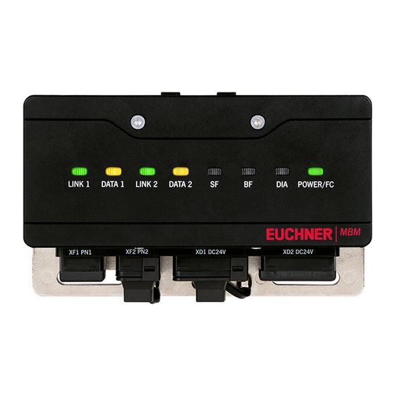
Correction by reintegration of the device; see AP000232, chapter 11.2. Example for the reintegration of POWER/FC the MBM F-I/O at www.euchner.com Color: green FC (fault code): indication of MLI connection faults Color: red 2500235-04-07/20 (Translation of the original operating instructions) -
Page 16: Electrical Connection
Operating Instructions Bus Module MBM-PN-..-MLI-… (PROFINET) 10. Electrical connection WARNING In the event of a fault, loss of the safety function due to incorrect connection. Ì Mounting must be performed only by authorized personnel. Ì Lay the connecting cables with protection to prevent the risk of short circuits. CAUTION Risk of damage to equipment or malfunctions as a result of incorrect connection. -
Page 17: Bus Connections
Operating Instructions Bus Module MBM-PN-..-MLI-… (PROFINET) 10.2. Bus connections The bus module MBM includes the PROFINET connections (XF1 and XF2) and the power supply connections (XD1 and XD2). Depending on version, connection is via Ì push-pull plugs according to IEC 61076-3-117, variant 14, or Ì... -
Page 18: Mli Connections
Operating Instructions Bus Module MBM-PN-..-MLI-… (PROFINET) 10.3. MLI connections The MLI connections are used to connect modules to the bus module MBM. The sealing caps can be reordered (complete set AC-SET-BP-M12, order no. 156739) Connection Description ML1D (direct plug) Module plug connector for direct mounting in a block. Important! Use only for direct mounting. -
Page 19: Remote Mounting
Operating Instructions Bus Module MBM-PN-..-MLI-… (PROFINET) 10.3.2. Remote mounting Pay attention to the following points on remote mounting: Ì The maximum cable length for a line must not exceed 40 m. Ì Up to 3 modules can be operated per line. If you require a different configuration, contact our technical support team. Ì... -
Page 20: Connecting Modules
No, must be ordered separately Module connector M12, 8-pin socket, for the connection of a stacklight 157029 Connecting cable M12, 5-pin See catalog or www.euchner.com Connecting cable M12, 8-pin * Not for MGB2-…-Y0000-… (Translation of the original operating instructions) 2500235-04-07/20... -
Page 21: Setup
Operating Instructions Bus Module MBM-PN-..-MLI-… (PROFINET) 11. Setup A typical MLI system usually consists of several modules and submodules. Which modules and submodules are used is determined by the bus module MBM on each system start. To suit this configuration, in the configuration software for your control system you must assemble the related data blocks for the communication data for the individual modules and submodules and, if necessary, set parameters. -
Page 22: Information On The Data Sheets Enclosed
Operating Instructions Bus Module MBM-PN-..-MLI-… (PROFINET) Bit identifiers for Bit identifiers for Description Description position [1] position [4] Data from bus modules MBM Switch 1, 2, … Data from interlocking/locking modules MGB2-I…/MGB2-L… Lamp 1, 2, … Data from submodules MSM Emergency stop Data from extension modules MCM Safe signal “Position of the bolt tongue”... -
Page 23: System Layout And Layout Of The Data Areas In The Control System
Operating Instructions Bus Module MBM-PN-..-MLI-… (PROFINET) 11.3. System layout and layout of the data areas in the control system Due to its modular layout, the MLI system offers you a very large degree of flexibility. This flexibility also applies to the use of the communication data. - Page 24 Operating Instructions Bus Module MBM-PN-..-MLI-… (PROFINET) The individual data blocks or bits are always combined in the same sequence as the system layout. Here the counting is always started at the bus module (1) and then continued from the first to the last module on a line. If there are two lines, the complete first line on MLC1 (2…4 in the figure below) is counted first and then the complete second line on ML2C (5…7 in the figure below).
-
Page 25: Profinet Data Bytes
Operating Instructions Bus Module MBM-PN-..-MLI-… (PROFINET) 11.4. PROFINET data bytes Each module or submodule sends specific, non-safe communication data. The following chapters provide an overview of the most important module types and their data. You can find item-specific information on which data blocks your modules or submodules contain in the data sheet that is enclosed with every device (see chapter 11.2. -
Page 26: Integrating Into Profinet And Profisafe
GSD file from TIA V14: GSDML-V2.33-EUCHNER-MBM_2512512_T14-YYYYMMDD.xml You will find the GSD file in the download area at www.euchner.com. Always use the latest GSD file. Prior to setup, the GSD file must be imported into the configuration software for the control system (see 11.6. -
Page 27: Configuring And Setting Parameters For Modules And Submodules
Operating Instructions Bus Module MBM-PN-..-MLI-… (PROFINET) 11.7. Configuring and setting parameters for modules and submodules To be able to use the individual modules and submodules, these must be configured and parameters set correspondingly in the configuration software for your control system. The following chapters describe these steps based on the example of the configuration software TIA-Portal from SIEMENS. - Page 28 V1.1.0 MGB2-L1-MLI-U-Y0000-BJ-136776 SAFETY SWITCH UNICODE ID.-Nr.: 136776 000001 V1.0.0 IP65 Fzh = 2000N EUCHNER GmbH + Co. KG FCC ID: 2AJ58-XX Kohlhammerstraße 16 IC: 22052-XX XX DE-70771 Leinfelden IND.CONT.EQ 7C77 TYPE 1 Input: 24 Vdc, Class 2 Output: 24 Vdc, 200mA...
- Page 29 Operating Instructions Bus Module MBM-PN-..-MLI-… (PROFINET) The figure below shows an example system layout. ML2C ML1C Figure 6: Example system layout 2500235-04-07/20 (Translation of the original operating instructions)
-
Page 30: List Of The Parameters That Can Be Set Per Module/Submodule
Device name Arbitrary designation The device name can be assigned as required. Important: It [EUCHNER-MBG] must match the name in the configuration software. Tip: On replacing a faulty device, it is recommended to delete the name in the device (factory setting). If there is no name in the device, the existing name in the system for the previous device is entered automatically on starting. -
Page 31: Replacing Submodules
Operating Instructions Bus Module MBM-PN-..-MLI-… (PROFINET) 11.8. Replacing submodules CAUTION Risk of damage to equipment or malfunction as a result of uncontrolled machine stop. Ì The communication within the system is interrupted by the replacement of a submodule, and the safe bits are reset. -
Page 32: Overview Of Data Blocks For Modules And Submodules
Operating Instructions Bus Module MBM-PN-..-MLI-… (PROFINET) 12. Overview of data blocks for modules and submodules Important! Ì You will find the exact data structure for your device on the data sheet enclosed. Ì With some modules and submodules, you have the choice between a standard configuration (basic) that has basic status, signaling and control functions or an extended configuration that also contains an additional byte with exact error codes for diagnostic purposes. -
Page 33: Data Blocks For Interlocking/Locking Module Mgb2-I / Mgb2-L
Operating Instructions Bus Module MBM-PN-..-MLI-… (PROFINET) 12.2. Data blocks for interlocking/locking module MGB2-I / MGB2-L 12.2.1. Safe bits Input/ Bit identifier Meaning Condition for setting Condition for resetting output LM.FI_SK Input Safe input Door closed and bolt tongue inserted into inter- Door open OR fault in transponder Door position locking/locking module... -
Page 34: Data Blocks For Extension Module Mcm
Operating Instructions Bus Module MBM-PN-..-MLI-… (PROFINET) 12.3. Data blocks for extension module MCM Extension modules can contain up to four submodules and evaluate them. They do not have any further dedicated function. 12.3.1. Safe bits Extension modules do not have any dedicated safe bits. 12.3.2. -
Page 35: Data Blocks For Submodules
Operating Instructions Bus Module MBM-PN-..-MLI-… (PROFINET) 12.4. Data blocks for submodules For which data blocks your submodule contains, refer to the data sheet enclosed with each submodule. See also chapter 11.2. Information on the data sheets enclosed. 12.5. Replacing a bus module MBM without programming device If servicing is required, the bus module MBM is easy to replace with a new module. -
Page 36: Diagnostics, Troubleshooting And Aids
Operating Instructions Bus Module MBM-PN-..-MLI-… (PROFINET) 13. Diagnostics, troubleshooting and aids All error codes are listed in the following. If you use the data blocks with extended configuration in the configuration software for your control system, the error code is output in the corresponding byte. In the standard configuration only a corresponding fault status bit is set and the system indicates the fault via the diagnostics LEDs. -
Page 37: Diagnostics With The Aid Of The Device Web Interface
Operating Instructions Bus Module MBM-PN-..-MLI-… (PROFINET) 13.4. Diagnostics with the aid of the device web interface The device has an internal device web interface. The device web interface can be used at any time in operation if the function is activated. It is not possible to make any settings on the device. The following diagnostics information is provided: Ì... - Page 38 The fault list can also be downloaded from the device. With this file, support will be able to provide specific assistance if you have problems. The download link is at the end of the fault list. Click ENVIRONMENT to display available environment parameters. Ì The password-protected SERVICE page can be accessed only for on-site support by EUCHNER. HOME FAULT-LOG ENVIRONMENT...
-
Page 39: General Faults
Operating Instructions Bus Module MBM-PN-..-MLI-… (PROFINET) 13.5. General faults LED indicators Interlocking/locking Bus mod- module Internal fault Internal device Internal fault Latching Restart system. If the fault 0x01 fault. Device is no persists, contact our support … LM.E_G longer functional. team. -
Page 40: Environment Errors
Operating Instructions Bus Module MBM-PN-..-MLI-… (PROFINET) 13.8. Environment errors LED indicators Interlocking/ Bus module locking module Supply voltage Overvoltage Environment Resetta- Reduce supply voltage. Pay too high error attention to technical data. 0x60 For MGB2 Supply voltage Low voltage Environment Resetta- Increase supply voltage or LM.E_G... -
Page 41: Plausibility Errors
Operating Instructions Bus Module MBM-PN-..-MLI-… (PROFINET) 13.10. Plausibility errors LED indicators Interlocking/locking module Plausibility error, Transponder for Plausibility error Resetta- Check function of the handle bolt fracture the bolt has been module. Pay attention to dam- 0x88 detected without the age. -
Page 42: Profinet Errors
Operating Instructions Bus Module MBM-PN-..-MLI-… (PROFINET) 14. Profinet errors LED displays Bus module Parameter The assembly has detected a Application fault Latching Check parameters and setting error parameter setting error. Param- correct these. Then load the eter setting errors can include: parameters into the assem- –... -
Page 43: Profisafe Errors
Operating Instructions Bus Module MBM-PN-..-MLI-… (PROFINET) 15. PROFIsafe errors LED displays Bus module F_DEST_ADDR Erroneous safety desti- Param- Latching The PROFIsafe address set on the device does not match nation address eter the address set in the parameters for your control system in 0x0150 setting the configuration tool. -
Page 44: Technical Data
Operating Instructions Bus Module MBM-PN-..-MLI-… (PROFINET) 16. Technical data NOTICE If a data sheet is included with the product, the information on the data sheet applies. Parameter Value Housing material Fiber glass reinforced plastic Die-cast zinc, nickel-plated, stainless steel, Dimensions See dimension drawing Weight, bus module 0.8 kg... -
Page 45: Calculation Example For Determining The Risk Time For Safe Functions
Operating Instructions Bus Module MBM-PN-..-MLI-… (PROFINET) 16.1. Calculation example for determining the risk time for safe functions Important! Only modules and submodules that contain a safety function flow into the calculation of the risk time. Safe modules and submodules are apparent because they transmit safe bits (PROFIsafe bits) via the bus module to the control system. -
Page 46: Service
Loss of the safety function because of damage to the device. In case of damage, the affected module must be replaced completely. Only accessories or spare parts that can be ordered from EUCHNER may be replaced. Regular inspection of the following is necessary to ensure trouble-free long-term operation: Ì... -
Page 47: Declaration Of Conformity
Operating Instructions Bus Module MBM-PN-..-MLI-… (PROFINET) 19. Declaration of conformity 2500235-04-07/20 (Translation of the original operating instructions) - Page 48 Operating Instructions Bus Module MBM-PN-..-MLI-… (PROFINET) (Translation of the original operating instructions) 2500235-04-07/20...
- Page 49 Operating Instructions Bus Module MBM-PN-..-MLI-… (PROFINET) 2500235-04-07/20 (Translation of the original operating instructions)
- Page 50 Operating Instructions Bus Module MBM-PN-..-MLI-… (PROFINET) (Translation of the original operating instructions) 2500235-04-07/20...
- Page 51 Operating Instructions Bus Module MBM-PN-..-MLI-… (PROFINET) 2500235-04-07/20 (Translation of the original operating instructions)
- Page 52 Edition: 2500235-04-07/20 Title: Operating Instructions Bus Module MBM-PN-..-MLI-… (PROFINET) from V1.0.0 (Translation of the original operating instructions) Copyright: © EUCHNER GmbH + Co. KG, 07/2020 Subject to technical modifications; no responsibility is accept- ed for the accuracy of this information.
Need help?
Do you have a question about the MBM-PN MLI Series and is the answer not in the manual?
Questions and answers