
Summary of Contents for Fischer Panda P6+
-
Page 1: Generator Control Panel P6+ Manual
Generator Control Panel P6+ Manual 12 V version - 0000139 24 V special version - 0000527 Option automatic adapter - 0000521 Option master-slave adapter - 0000133 Panel Generator Control P6+ RE0703_Kunde_eng.R10 10.5.17... -
Page 2: Current Revision Status
Reproduction and modification of the manual is permitted only after agreement with the manufacturer! Fischer Panda GmbH, 33104 Paderborn, reserves all rights regarding text and graphics in this document. Details are given to the best of our knowledge. No liability is accepted for correctness. Please note: technical modifications aimed at improving the product may be implemented without prior notice. -
Page 3: Table Of Contents
The Automatic input: ......................20 2.6.3 Terminal connections ....................... 21 Master-Slave adapter - optional ..................21 2.7.1 Fischer Panda Art. No. 21.02.02.015P, 12 V-version ............21 2.7.2 Fischer Panda Art. No. 21.02.02.015P, 24 V-version ............22 2.7.3 Terminal connections: ...................... 22 2.7.4... - Page 4 Leere Seite / Intentionally blank Seite/Page 4 Kapitel/Chapter 1: 10.5.17...
-
Page 5: Safety Instructions Generator Control P6
1. Safety Instructions Generator Control P6+ 1.1 Personal requirements The settings described here can by performed by the operator, unless otherwise indicated. The installation should be carried out by specially trained personnel or by authorized repair shops (Fischer Panda service points). 1.2 Safety instructions... - Page 6 Safety Instructions Generator Control P6+ Note also the safety of the other components of your Note! system. Seite/Page 6 - Kaptitel/Chapter 1: Safety Instructions Generator Control P6+ 10.5.17...
-
Page 7: General Operation
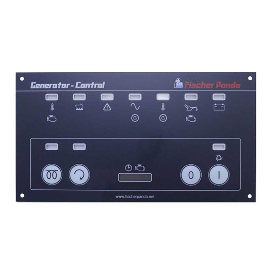
General operation 2. General operation 2.1 Panel Generator Control Fischer Panda Art. No. 21.02.02.046P Fig. 2.1-1: Panel front 01. LED for coolant temperature red 08. LED for pre-glow „heat“ orange 02. LED for water leak red/yellow (sensor optional) 09. LED for Generator „start“ green 03. -
Page 8: Rear View 12 V-Version
General operation 2.1 Rear view 12 V-version Fischer Panda Art. No. 21.02.02.046P Fig. 2.1-1: Panel rear view 12 V-version 01. Control board 02. Terminal block (master-slave adapter: left row; automatic adapter: right row) 03. Terminals 1-12 (see section 2.3.2, “Terminal connections,” on page 10) 04. -
Page 9: Rear View 24 V-Version
General operation 2.2 Rear view 24 V-version Fischer Panda Art. No. 21.02.02.047P Fig. 2.2-1: Panel rear view 24 V-version 01. Control board 02. Terminal block (master-slave adapter: left row; automatic adapter: right row) 03. Fuse 630 mA slow-blow 04. Terminals 1-12 (see section 2.3.2, “Terminal connections,” on page 10) 05. -
Page 10: Installation Of The Remote Control Panel
General operation 2.3 Installation of the remote control panel 2.3.1 Placement. Install the remote control panel at a dry, good accessible and shady place. Connect the remote control panel to the standard 12 core cable at the generator. (1:1) 2.3.2 Terminal connections Standard for NC temperature switch configured i.e. -
Page 11: Function Of The Jumpers
General operation Clamp no. Clamp name IN / OUT Description T-Winding Error “winding temperature”. Input for thermo-switch to GND. The input is adjustable for NC/NO (N = no error) (must be adjusted by solder Jumper). The input loads the switch with 22 mA to +12 V (with 24 V-operated internally generated). -
Page 12: Configuration And Adjustment
General operation 2.3.4 Configuration and adjustment 2.3.4.1 Configuration and setting sheet KE01 Standard jumpering for generators with three-phase DC-alternator (Kubota Super 5 series). Panel only for 12 V-operation. The safety device is installed with the value 0,63 AT. The circuit parts for 24 V-operation are not equipped. Fig. -
Page 13: Configuration And Setting Sheet Ke02
General operation 2.3.4.2 Configuration and setting sheet KE02 Standard jumpering for generators with three-phase DC-alternator. Panel for 24 V-operation (over attitude of solder jumper J101 alternatively 12 V-operation is possible). The safety device is installed with the value 0,63 AT. The circuit parts for 24 V-operation are not equipped. -
Page 14: Configuration And Setting Sheet Ke03
General operation 2.3.4.3 Configuration and setting sheet KE03 Standard jumpering for generators with DC-alternator. Panel only for 12 V-operation. The safety device is installed with the value 0,63 AT. The circuit parts for 24 V-operation are not equipped. Fig. 2.3.4.3-1: Settings of soldered jumper for this configuration (column Conf.) Jumper Status Conf. -
Page 15: Configuration And Setting Sheet Ke04
General operation 2.3.4.4 Configuration and setting sheet KE04 Standard jumpering for generators with DC-alternator. Panel for 24V-operation (over attitude of solder jumper J101 alternatively 12 V-operation is possible). The safety device is installed with the value 0,63 AT. The circuit parts for 24 V-operation are not equipped. Fig. -
Page 16: Starting Preparation / Checks (Daily)
General operation 2.4 Starting preparation / Checks (daily) 2.4.1 Marine version 1. Oil level control (ideal level: 2/3 MAX). The level should be about 2/3 of the maximum level of a cold engine. Further, if installed, the oil level of the oil-cooled bearing must be controlled before each start - see sediment bowl at generator front cover!. -
Page 17: Starting And Stopping The Generators
General operation 2.5 Starting and stopping the generators 2.5.1 Starting the generator Danger for life! - The generator can be equipped with a Warning!: Automatic start automatic start device. This means the generator can be started by an external signal. To avoid an unexpected starting of the generator, the starter battery must be dis- connected before start working at the generator. -
Page 18: Stopping The Generator
General operation In the event of starting problems, close the sea water Attention! inlet cock. Panda marine generators only. Should there be any reason to turn the engine (over) or start the engine i.e. to bleed the fuel system, the sea water inlet cock must be closed! During the starting process, the cooling water pump is driven with the motor. -
Page 19: Automatic Adapter - Optional
General operation 2.6 Automatic adapter - optional Fischer Panda Art. No. 21.02.02.016P Fig. 2.6-1: Panel 21.02.02.046P with Automatic adapter 21.02.02.016P 01. Main terminals 02. Automatic adapter 21.02.02.016P 03. 8-pole DIP-switch 2.6.1 Function: The automatic adapter RE0704 extends the generator control panel P6+ with an automatic input. A potential-free contact can be attached to this input. -
Page 20: The Automatic Input
General operation 2.6.2 The Automatic input: With (-) characterized connection is connected to GND. With (+) characterized connection is the input. The input is connected through a resistance to 12 V (with 24 V-operated internally generated). If the two connections are short circuited over a potential-free contact, then the input current flows. -
Page 21: Terminal Connections
2 s, after switching on the panel) power supply - (ground) 2.7 Master-Slave adapter - optional 2.7.1 Fischer Panda Art. No. 21.02.02.015P, 12 V-version Fig. 2.7.1-1: Panel 21.02.02.046P with master-slave adapter 21.02.02.015P 01. Main terminals 02. Master-slave adapter 21.02.02.015P 10.5.17... -
Page 22: Fischer Panda Art. No. 21.02.02.015P, 24 V-Version
General operation 2.7.2 Fischer Panda Art. No. 21.02.02.015P, 24 V-version Fig. 2.7.2-1: Panel 21.02.02.047P with master-slave adapter 21.02.02.015P 01. Main terminals 02. Master-slave adapter 21.02.02.015P With the Master-Slave-Adapter RE0706 two Generator Control Panels P6+ RE0703 can be connected to a Master- Slave-Combination. -
Page 23: Terminal Connections
General operation 2.7.5 Terminal connections 2.7.5.1 Terminal X2 (IN/OUT from view Master-Operating-Panel) Fig. 2.7.5-1: Terminal connections terminal X2 (IN/OUT from the view of the master-control-panel) Pin-No. Pin-name IN / OUT Description power supply + (operation voltage behind fuse 12 Vdc or 24 Vdc depending on system) power supply - (ground) ON-Signal I / O... -
Page 24: Configuration And Adjustment
General operation 2.7.6 Configuration and adjustment 2.7.6.1 Configuration and setting sheet KE05 Standard jumpering for use as Slave-Panel in connection with two Master-Slave-Adapters RE0706 and a Generator Control Panel P6+ RE0703 as Master-Panel. Panel only for 12 V-operation. The safety device is installed with the value 0,63 AT. The circuit parts for 24 V-operation are not equipped. Fig. -
Page 25: Configuration And Setting Sheet Ke06
General operation 2.7.6.2 Configuration and setting sheet KE06 Standard jumpering for use as Slave-Panel in connection with two Master-Slave-Adapters RE0706 and a Generator Control Panel P6+ RE0703 as Master-Panel. Panel for 24 V-operation. (over attitude of solder jumper J101 alternatively 12 V-operation is possible) The safety device is installed with the value 0,63 AT. - Page 26 General operation Leere Seite / Intentionally blank Seite/Page 26 Kapitel/Chapter 2: General operation 10.5.17...
-
Page 27: Measurements
Measurements 3. Measurements 3.1 Hole pattern Fig. 3.1-1: Hole pattern 10.5.17 Kapitel/Chapter 3: Measurements - Seite/Page 27... - Page 28 Measurements Leere Seite / Intentionally blank Seite/Page 28 Kapitel/Chapter 3: Measurements 10.5.17...
Need help?
Do you have a question about the P6+ and is the answer not in the manual?
Questions and answers