Advertisement
Quick Links
INSTALLATION AND CONNECTION
This section contains the instructions necessary mfor correct installation of the GF_PROMER into the machine
control panel or the host system and for correct connection of the controller power supply, inputs, outputs and
interfaces.
Before proceeding with installation read the following warnings carefully! Remember that lack of observation of
these warnings could lead to problems of electrical safety and electromagnetic compatibility, as well as invalida-
ting the warranty.
ELECTRICAL POwER SUPPLy
• the GF_PROMER is NOT equipped with an On/Off switch: the user must provide a two-phase disconnecting switch that
conforms to the required safety standards (CE marking), to cut off the power supply upstream of the controller.
The switch must be located in the immediate vicinity of the controller and must be within easy reach of the operator.
One switch may control more than one instrument.
• if the controller is connected to NOT isolated electrical equipment (e.g. thermocouples), the earth connection must be
made with a specific conductor to prevent the connection itself from coming directly through the machine structure.
• if the programmer is used in applications with risk of damage to persons, machinery or materials, it is essential to be
connect it up to auxiliary alarm equipment.
It is advisable to make sure that alarm signals are also triggered during normal operation.
The controller must NOT be installed in flammable or explosive environments; it may be connected to equipment
operating in such atmospheres only by means of appropriate and adequate types of interface, conforming to the
applicable safety standards.
NOTES CONCERNING ELECTRICAL SAFETy AND ELECTROMAGNETIC COMPATIbILITy:
CE MARKING: EMC Conformity (electromagnetic compatibility) in accordance with EEC Directive 2004/108/CE.
The programmers series are mainly designed to operate in industrial environments, installed on the switch boards or
control panels of productive process machines or plants.
As regards electromagnetic compatibility, the strictest generic standards have been adopted, as indicated in the table
below.
bT Conformity (low voltage) in accordance with Directive 2006/95/CE.
EMC conformity has been tested with the following connections (table 1 (see "Installation and operation manual").
FOR A CORRECT "EMC" INSTALLATION
Instrument power supply
Installation category II and pollution degree 2.
• The power supply to the electronic equipment on the switchboards must always come directly from an isolation device
with a fuse for the instrument part.
• The electronic instruments and electromechanical power devices such as relays, contactors, solenoid valves, etc.,
must always be powered by separate lines.
ELECTRICAL CONNECTIONS / USER CONNECTIONS
GF_PROMER 35 connector
GF_PROMER 57 connector
Name
Description
1
Power supply
2
USB
3
Ethernet 10/100
4
Serial RS485
5
BUS-G
6
Rotary-switch
7
Enabling battery
The user connections specified on Table are made at the bottom
by means of Gefran standard and custom connectors.
• When the electronic instrument power supply is strongly disturbed by voltage problems from power units or motors, an
isolation transformer should be used for the controllers only, earthing the screen.
• It is essential that the plant has a good earth connection:
- the voltage between neutral and earth must not be >1V
- the resistance must be <6Ω;
• If the mains voltage fluctuates strongly, use a voltage stabilizer.
• In the proximity of high frequency generators or arc welders, use adequate mains filters.
• The power supply lines must be separate from the instrument input and output lines.
Inputs and outputs connection
• To connect the analogue inputs, strain gauge, linear, (TC, RTD) the following is necessary:
- physically separate the input cables from those of the power supply, the outputs and the power connections.
- use woven and screened cables, with the screen earthed in one point only.
• To connect the control outputs, alarm (contactors, solenoid valves, motors, fans, etc.), fit RC groups (resistance and
condensers in series) in parallel to the inductive loads that operate in Alternating Current.
(Note: all the condensers must conform to VDE (class X2) standards and withstand a voltage of at least 220V AC. The
resistances must be at least 2W).
• Fit a 1N4007 diode in parallel with the coil of the inductive loads that operate in Direct Current.
GEFRAN S.p.A. declines all responsibility for any damage to persons or property caused by tampering,
neglect, improper use or any use which does not conform to the characteristics of the controller and to
the indications given in these Instructions for Use.
Prescription UL
- Operating surrounding air temperature rating of 50°C
- For use on a flat surface of a type 1 enclosure
The instrument conforms to the European Directives 2004/108/CE and 2006/95/CE with
reference to the generic standards: EN 61131-2 (Product) EN 61010-1 (safety)
24Vdc supply.
The internal power supply 24Vdc is galvanically isolated and protected against
polarity reversal and short circuits. The panel has a power terminal.
The connector diagram is shown in Figure.
Note: check that the power supply is able to deliver the power needed for correct
operation of the device.
The device must always be grounded.
Grounding helps limit the effects of electromagnetic noise on the control system.
All electronic devices of the control system must be grounded.
Ground the devices in a manner conforming to applicable standards and regulations.
Max consumption.GF_PROMER 35:
Max consumption.GF_PROMER 57:
• (without I/O) 240mA, 5W
• (without I/O) 480mA, 8,5W
• (with I/O) 360mA, 7W
• (with I/O) 490mA, 9W
Pin
Name
Description
1
+24 VDC
Positive feed
2
0 V
GND
3
GND
Ground
Inserting cores in the power supply lines of GF_PROMER 57
To limit susceptibility to noise of the GF_PROMER 57 programmer you have to install an
electromagnetic emission suppression core as shown in figure.
This component, supplied with the product, is a ferrite core coated in plastic for round section
wires.
INSTALLATION AND OPERATION MANUAL
Side 1
Installation and Connection
Electrical connections
Side 2
Technical information
Dimensions
Fixing/Installation
via Sebina, 74 - 25050 Provaglio d'Iseo (BS)
Tel. 03098881 - fax 0309839063- Internet: http://www.gefran.com
Length and type of connection cable between GF_PROMER and GFX / GFX4 / GFX4-IR / GFXTERMO4 units:
Power supply connector
- standard telephone up to 10m
1
2
3
- shielded cable up to 150m (shield to GND)
- woven and shielded cable (Belden, shield to GND) for distances > 150m up to a maximum of 1200m
Connector of the RS-485 port
1
4
Ethernet port connections
+24Vcc ±25%
1
8
Green
Yellow
0V
+24V
Led
Color
Description
Sx
Green
Link
Dx
Yellow
Data
Rotary switch for setting Ethernet node ID
The terminals let you set the Ethernet node ID via a user-accessible 16-position rotary
1 2 3
switch.
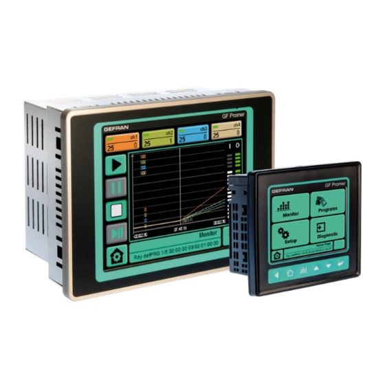
GF_PROMER
Graphic setpoint programmer, 4 zones
3.5" and 5.7" screens, TFT, Colour, Touch screen
code 80327 - 01/2012 - ENG
GEFRAN spa
Signal assignment of the RS-485 port
Pin
Name
Description
1
GND
-
2
Tx/Rx +
Data reception/transmission (A+)
3
Tx/Rx -
Data reception/transmission (B-)
4
+V (reserved)
-
Signal assignment of the Ethernet port
Pin
Name
Description
1
TX_D+
Tranceive data +
2
TX_D-
Tranceive data -
3
RX_D+
Receive data +
4
N.C.
Not connected
5
N.C.
Not connected
6
RX_D-
Receive data -
7
N.C.
Not connected
8
N.C.
Not connected
Advertisement

Related Manuals for gefran GF PROMER 35

Summary of Contents for gefran GF PROMER 35
- Page 1 INSTALLATION AND OPERATION MANUAL NOTES CONCERNING ELECTRICAL SAFETy AND ELECTROMAGNETIC COMPATIbILITy: GEFRAN S.p.A. declines all responsibility for any damage to persons or property caused by tampering, CE MARKING: EMC Conformity (electromagnetic compatibility) in accordance with EEC Directive 2004/108/CE. neglect, improper use or any use which does not conform to the characteristics of the controller and to...
- Page 2 GF_PROMER 35 DIMENSIONS TECHNICAL SPECIFICATION All measurements are expressed in mm, with tolerance of ± 0.5. Display Weight (Kg) 0,4 (35CT) 0,8 (57CT) Type TFT color With 2 modules GilogikII (Kg) 0,7 (35CT) 1,1 (57CT) Number colors 262K Front dimensions (mm) 100x100x64 (35CT) 169x120x76 (57CT) Protection IP65 Diagonal...