Advertisement
Table of Contents
- 1 Table of Contents
- 1 Chapter 1: Overview
- 2 Chapter 2: Site Survey and Connectivity Test
- 3 Chapter 3: Antenna Installation
- 4 Chapter 4: RTU Installation and Wiring
- 5 Chapter 5: RTU Startup
- 6 Chapter 6: Test the Installation
- 7 Chapter 7: Site Commissioning
- 8 Appendix A: Terminology
- 9 Appendix B: Solid State Relay Wiring Diagram
- Download this manual
Advertisement
Table of Contents

Related Manuals for Mission MyDro M150


Summary of Contents for Mission MyDro M150
- Page 1 150/850 Installation Manual PMS 660...
- Page 2 Twitter updates. Mission Technical Support is available 24-7-365 on a responsive callback basis for after- hour emergencies at (877) 993-1911 option 2 or techsupport@123mc.com. Please have the customer name and appropriate unit serial number ready.
-
Page 3: Table Of Contents
Contents Chapter 1: Overview Chapter 2: Site Survey and Connectivity Test Chapter 3: Antenna Installation Chapter 4: RTU Installation and Wiring Chapter 5: RTU Startup Chapter 6: Test the Installation Chapter 7: Site Commissioning Appendix A: Terminology Appendix B: Solid State Relay Wiring Diagram... -
Page 4: Chapter 1: Overview
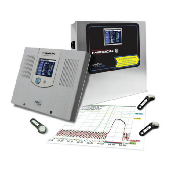
Chapter 1: Overview M150/M850 at a Glance Each RTU is packaged with everything necessary for a standard installation Enclosures NEMA 1—indoor mounting NEMA 4X—outdoor mounting FlatPak—control panel inner door mounting FlatPak Retrofit—(convert M110 or M800 to MyDro) Hardware Included with RTUs RTU with NEMA 1, NEMA 4X, or FlatPak enclosure RTU Installation Packet: RTU Form, User Guide, and emergency notice label Battery—12 volt, 5 amp-hour... - Page 5 Ladder (for antenna mounting) Available Input/Output Expansion Mission offers a variety of expansion modules to extend the utility of the RTU. Available options are summarized below: • Safe Module Plus: intrinsically safe float circuit, local relay, 4 pulse channels • Digital Input: adds 8 channels •...
-
Page 6: Chapter 2: Site Survey And Connectivity Test
(red) lead. Once the sequence is completed, you will hear three beeps from the buzzer. This indicates the unit has connected to Mission servers. If the RTU does not connect after two attempts, call Technical Support. - Page 7 Figure 1: Main Printed Circuit Board Wired for Site Survey...
-
Page 8: Chapter 3: Antenna Installation
The coaxial cable should reach the Mission RTU radio connection with no severe routing of the coaxial cable. Consider where the RTU will be mounted in relation to the location of the antenna. - Page 9 • Signal cables should not run parallel with high voltage AC wires (load conductors). • Where signal wires and load conductors must cross, do so at right angles. • High voltage should not enter the Mission RTU. Mount the supplied transformer outside the Mission enclosure.
-
Page 10: Chapter 4: Rtu Installation And Wiring
2. Cut the conduit and wiring holes. Drill and but leave space for the attach the conduit in the control cabinet included battery. and Mission RTU. Use sealant where appropriate. NEMA 1 3. Pull the wires and cables. Use indoors where no wash-downs occur. - Page 11 You may use either N/O or normally closed N/C contacts on digital inputs 4 through 8. Notify Mission Technical Support (or indicate on RTU setup form) to change the default settings (refer to Figure 2).Connect the shields of digital input wires to the grounding lug located inside the RTU.
- Page 12 Figure 2: Digital Inputs—Current Sensor, Supervision, and Surge Suppression Wire fault supervision: EOL resistors are optional with the MyDro. When utilized and installed properly (at the far end of the cable wired parallel to the switch) they allow the system to alarm on a wire fault. Software selection of this is done from the touch screen.
- Page 13 Config. Menu/Relay Comm Fail Setup as Deenergize or No Change. Warning: If power to output relays is supplied by Mission auxiliary power port it is software configurable as 12 or 24 VDC. Specify coil voltage of interposing relays appropriately.
- Page 14 AC in connection (see Figure 4B). Mount the transformer in the control panel (not the Mission RTU). It is very important to only provide 12–16 VAC to the Mission mainboard AC input. Hooking up the transformer backwards will apply 1200 VAC to the mainboard and cause permanent damage.
-
Page 15: Chapter 5: Rtu Startup
Chapter 5: RTU Startup 1. Power the Mission RTU with the 12 VDC battery only. Connect the black lead first, then the red lead (see Figure 6). The LCD will illuminate the start up screen. Once the radio sequence is complete, you will hear three beeps from the buzzer. This indicates the unit has connected to Mission servers. - Page 16 Figure 7: Test the Installation...
-
Page 17: Chapter 6: Test The Installation
A smartphone can be used otherwise. 6. Test the pump runtime inputs. Turn on pump 1. Mission D1 should respond on the touch screen. If not, check the wiring and/or end-of-line resistors. Repeat step for pump 2 and 3, if used. - Page 18 Notification Setup form. Go to the Alarms page. You should see a list of alarm events with event time and the result. Call Mission Technical Support after testing the installation to enable the device for alarm call-outs. A technician will verify proper operation of equipment.
-
Page 19: Chapter 7: Site Commissioning
Mission hosts weekly webinars nearly every Wednesday at 2 P.M. Eastern. The revolving series covers the basics, advanced web portal options, and everything in between. Mission wants to help you get the most out of your system, so please join and feel free to ask questions. -
Page 20: Appendix A: Terminology
Multiple M850s can be linked so an event at one station causes a relay change at another. Mission’s Tank and Well Control option and Intertie rely on this feature. Consult Best Practices for Remote Control Digital Intertie for more information (123mc.com/literature). - Page 21 Pulse inputs can be used to report data such as flow, water meter, or rainfall totals. If no rainfall data is monitored at the site, Mission’s web site presents data from the closest National Weather Service reporting station. Four pulse inputs are available with the Safe Module Plus.
-
Page 22: Appendix B: Solid State Relay Wiring Diagram
Appendix B: Output Relay Diagram... - Page 23 Installation Notes...
- Page 24 Q&A. Training Tutorials A variety of videos are provided to cover topics relating to the use of the Mission system. These can be found on the 123SCADA web portal as well as the marketing website. Newsletter The quarterly newsletter provides useful information for water and wastewater professionals.
Need help?
Do you have a question about the MyDro M150 and is the answer not in the manual?
Questions and answers