Table of Contents
Advertisement
LED controller Advanced
OPPF series
Instruction Manual
- Thank you for the purchase of the LED controller Advanced "OPPF series."
- Before using it, please read this manual carefully to ensure proper use.
- After reading this manual, keep it carefully in an easily accessible location for future reference.
- This product should not be used as safety equipment intended for the protection of human
body.
- The warranty period of this product is one year after delivery. - Notwithstanding the above, any
fault attributable to natural disasters or any other similar disasters or undue alteration or repair
will be excluded from the scope of the warranty.
Ramco National
800-280-6933 | nsales@ramcoi.com
www.Optex-Ramco.com
Advertisement
Table of Contents

Summary of Contents for OPTEX FA OPPF Series
- Page 1 OPPF series Instruction Manual - Thank you for the purchase of the LED controller Advanced “OPPF series.” - Before using it, please read this manual carefully to ensure proper use. - After reading this manual, keep it carefully in an easily accessible location for future reference.
-
Page 2: Table Of Contents
Introduction Contents ● Introduction Features ● Contents LED controller Advanced “OPPF series” ● Compatible with two modes, including PWM lighting and strobe lighting. ● For Safe Use of the Product ● Capable of lighting brightness/temperature monitoring and feedback control by utilizing “FALUX sensing.” ● The external brightness control is compatible with three communication modes of RS232, parallel and analog 0-5 V. -
Page 3: For Safe Use Of The Product
The operating ambient temperature range of condensation may occur. ● In any of the following cases, immediately turn the OPPF series is 0-45°C. Take the following Housing hole dimension: ● Do not wipe it with wet rag and do not use into consideration. -
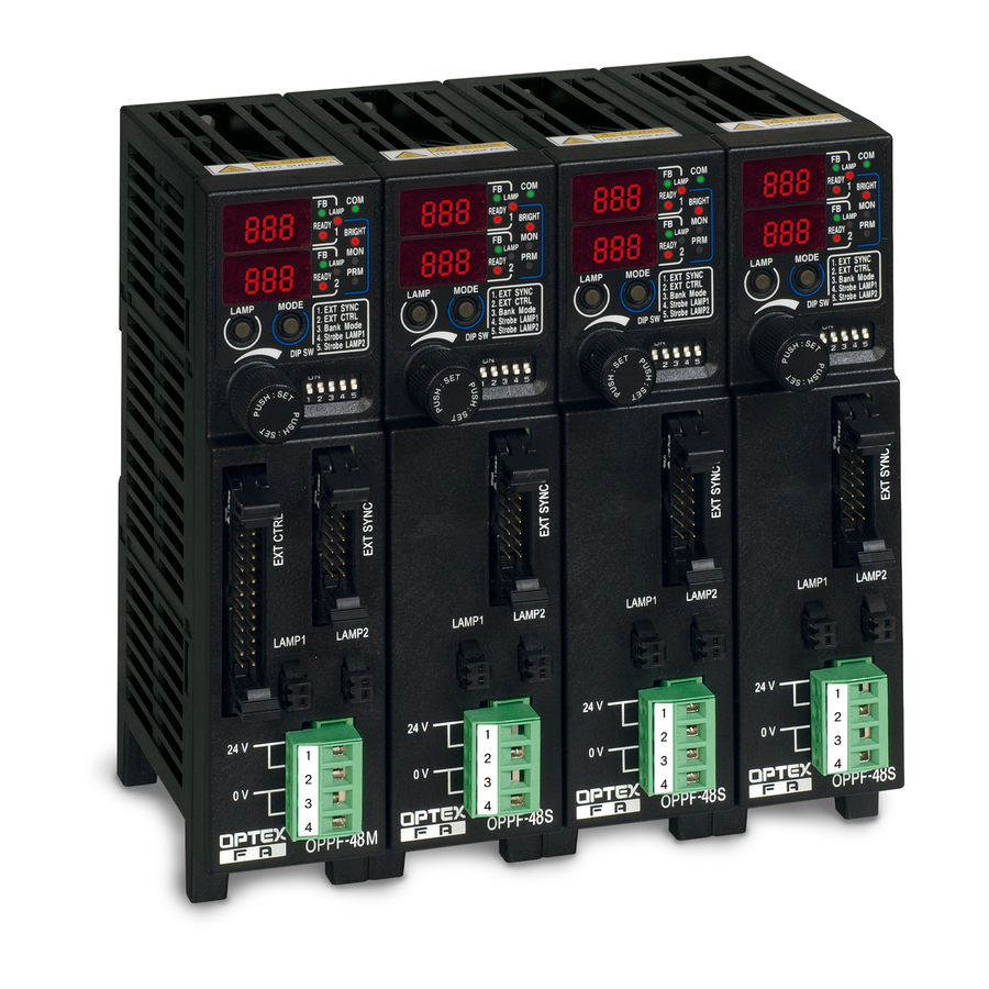
Page 4: Components And Their Functions
Components and Their Functions READY indicator Operation panel Display of FB (feedback) state Master Unit and Slave Unit Red: lighting ready Green: FB working Flashing red: LED output over current or LED Flashing orange: FB error or alarm on over heat OPPF-30M□ OPPF-30S□ monitored brightness Unlit: insufficient input voltage of 24V DC Red: communication with the lamp Master unit Slave unit... -
Page 5: Connecting Cables
Connecting Cables Infrared Communication Connecting Cables Major Functions of Infrared Communication between Master and Slave Units 24V DC input (power supply) - Copy of setting onto the slave unit by the operation on the master unit (setting cPy) Connector Omron socket 4-pole type All settings of the master unit’s LAMP1 are copied into LAMP2 of the master unit and LAMP1 and LAMP2 of all XW4B-04C1-H1 slave units. A long press on the mode button on the operation panel causes the transition to the “PRM setting Applicable wire 0.2 - 2.1 mm2, 24 - 14AWG 24V DC... -
Page 6: Pwm Brightness Control And Strobe Mode
Strobe Mode When the DIP SW4 (LAMP1) or DIP SW5 (LAMP2) is set ON, the equipment will work in the strobe mode. With the OPPF series, connecting a FALUX sensing-compatible lighting device makes it possible Use the value setting dial to set the brightness value (0 - 999). -
Page 7: Monitoring And Feedback Functions
Monitoring and Feedback Functions Setting Procedures Patent pending Usage (2) Operation Flowcharts Feedback Function For setting each setting, see the flowcharts shown below. Set the setting Fb to on. Set bAL to the lower limit value (%) Communication OPB-S or any other of the monitored brightness for alarm release (optional). Brightness control/lighting control FALUX sensing The output voltage will be adjusted to maintain the Power supply compatible lighting... -
Page 8: Setting The Brightness Control Values
Setting Procedures Setting the Brightness Control Values Indication Name Range Initial value Unit CH1,2 Details Besides the dial-based setting, the methods of setting the With the brightness control values set in the banks in This function is to adjust the voltage applied to the lighting device so the brightness control value include the use of external signal input. -
Page 9: List Of Input And Output Functions
Input & output List of Input and Output Functions Timing Chart - Master unit MIL 26 pin connector EXT CTRL Shown below are the timing charts for the brightness control value setting and the bank switching in the external parallel input. Pin number Name Input & output Signal name Details MIL26 In case of the external brightness control (DSW2 ON) and not input Brightness control bit 0/bank switching 0 Pin connector... -
Page 10: Rs232 Communication
RS232 Communication RS232 communication is performed using the pins 24 through 26 of the MIL 26 pin connector. List of Commands Baud rate 9600 bps (initial value). Changeable in the PRM setting change mode. (OFF/ 4800/ 9600/ 19200/ 38400/ 57600/ 115200) When writing data, the data are once written locally for comparison with those read from the EEPROM. Data length 8bit If they differ from each other, the data are written onto the EEPROM. Station number Master unit Slave unit Slave unit Slave unit Stop bit 1bit Parity None LAMP1 Flow control None LAMP2 Data Contents Read ( ʻRʼ... -
Page 11: Circuit Diagram
Circuit diagram Standard type TTL type NPN type : for master unit only NPN type : for master unit only OPPF-30□N OPPF-30□N-TTL 5 - 24V 5 - 24V L0-2 L0-2 Power supply 12V rated Power supply PWM switch 12V rated Variable Variable 6.8k PWM switch LAMP1+ 6.8k LAMP1+ Voltage Voltage D0-9 D0-9 supply supply Signal Signal (NPN output) (NPN output) detector detector COMINA COMINA Over current Over current ... -
Page 12: Troubleshooting
Troubleshooting Dimensions Check items Symptom Does not power ON. ・ Is the power cable properly connected? Is the capacity of the 24V DC power supply sufficient? ・ Is there any deficiency with the 24V DC input voltage? ・ Is the polarity of the 24V DC input correct? ・ Is there any wrong polarity for the transmission of power across units? Top view ・ Isnʼt there any transition wiring through the power connector that is not connected to a unit? Lighting device does not illuminate. ・ Are the connectors of the lighting device properly connected? ・ Isnʼt the brightness control value set at 0? ・ Isnʼt the unit set in the external lighting control mode (DSW1: ON)? ・ Isnʼt the LED output over current error? Unable to control the brightness. ・ Isnʼt it in a locked state? Unlock it. (See page 7 for the unlocking method.) ・ Isnʼt the unit set in the external brightness control mode (DSW2: ON)? Front view Side view Rear view Unable to change the settings. ・ Isnʼt it in a locked state? Unlock it. (See page 7 for the unlocking method.) φ4.5 ・ Is there any wrong designation of station number for the external control? Erroneously illuminates or ... -
Page 13: Specifications
Specifications Part number Part number OPPF-30MN OPPF-30MP OPPF-30SN OPPF-30SP OPPF-30MN-TTL OPPF-30MP-TTL OPPF-30SN-TTL OPPF-30SP-TTL Type Type Master unit NPN Master unit PNP Slave unit NPN Slave unit PNP Master unit NPN Master unit PNP Slave unit NPN Slave unit PNP Power supply 24V DC±10% Input External synchronous inputs: 2, Analog/Digital switch: 1, Parallel External synchronous inputs: 2, Power dissipation input for brightness control: 10 (4 are used for switching Bank), Feedback OFF: max. 1.8 A, feedback ON: max. 2.5 A, Analog/Digital switch: 1 Write signal for parallel input: 1, Channel switch: 3 Lighting output Output power PWM mode: up to 30 W (total for 2 channels), strobe mode: up to 15 W (per channel) Turn-ON voltage: 2 V or over, turn-OFF voltage: 0.9 V or lower, PWM mode: 12V DC (standard), strobe mode: 18V DC (standard) Synchronous input maximum input voltage: 16 V, input impedance: 1kΩ, insulated Output voltage (TTL) Response time (actual) In case of 3 V (OFF→ ON: 8 μs, ON → OFF: 70 μs) ...
Need help?
Do you have a question about the OPPF Series and is the answer not in the manual?
Questions and answers