Advertisement
Quick Links
IMPORTANT NOTE:
Read and understand the instructions before installing, operating, or maintaining this equipment. This
product is designed to be a component of a customized control system. It is the responsibility of each
customer to ensure the correct overall functionality of its systems and machines. SCI, its subsidiaries
and affiliates are not in a position to guarantee all of the characteristics of a given system or product not
designed by SCI.
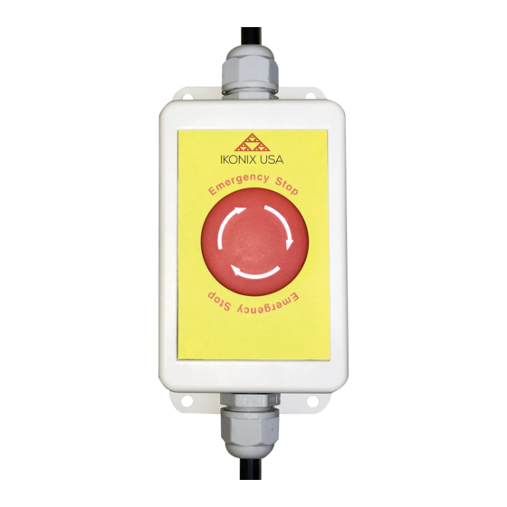
Operation
Emergency Stop Switches are mounted and used in line with the input power controlling an SCI safety
tester. Its intended function is to avert harm or to reduce existing hazards to persons, machinery, or work
in progress. The E-Stop should be triggered when an immediate hazardous situation occurs that needs
to be ended or averted quickly in order to prevent injury or damage. To trigger E-Stop press down on
mushroom cap, tthis will immediately cut power to the connected tester. To release the E-Stop rotate the
cap clockwise. This will immediately close the connection and provide power to the connected tester.
WARNING :
Device under test may still be charged after E-Stop has been
enabled. Take appropriate measure's to discharge any devices which may
hold capacitive charge.
Installation guide
Step 1 - When choosing a mounting position, consider your input power source i.e. nearest
wall outlet and electrical instrument location.
Use pre-drilled holes to mount the E-Stop enclosure to desired location.
See page 3 for enclosure spacing and measurements.
Step 2 - Connect female end of E-Stop to the
tester you wish to control.
Maintenance
Routinely verify functionality of switches and control circuits. Check for damage to push-button and enclosure.
© 2020 Ikonix USA
28105 North Keith Drive, Lake Forest, IL 60045 USA
•
Page 1 • ESTOP-INST V1.01 | 7.2020
E-Stop Instruction Sheet
Emergency Stop Switch • P/N ESTOP
Step 3 - Connect male end of E-Stop
to input power.
Advertisement

Related Manuals for IKONIX SCI E-Stop

Summary of Contents for IKONIX SCI E-Stop
- Page 1 Maintenance Routinely verify functionality of switches and control circuits. Check for damage to push-button and enclosure. © 2020 Ikonix USA 28105 North Keith Drive, Lake Forest, IL 60045 USA • Page 1 • ESTOP-INST V1.01 | 7.2020...
- Page 2 Enclosure IP65 rated Contact Switch EN 60947-5-5/A1:2005 EN 60947-5-1/A1:2009 ANSI/UL 508 145mm Screw Hole Size 56mm 56mm 100mm 134mm © 2020 Ikonix USA 28105 North Keith Drive, Lake Forest, IL 60045 USA • Page 2 • ESTOP-INST V1.01 | 7.2020...