
Related Manuals for Setma RGB-LE-V3.1


Summary of Contents for Setma RGB-LE-V3.1
- Page 1 Updated date: 2016.01.13 Model: RGB-LE-V3.1 E09PO28002 PCM2-911 Specification & Installation Compatible with Porsche PCM2.1 in sports vehicles (911, Boxster)
-
Page 2: Table Of Contents
Contents 1. Before installation 1.1 Main specification 1.2 System diagram 1.3 Components 1.4 Exterior 2. Setup 2.1 DIP switch 2.2 Remote controller 2.3 Power cable wiring diagram 3. Installation 3.1 Installation diagram 3.2 Cautions on installation 4. Troubleshooting... -
Page 3: Main Specification
1.1 Main Specification 1. Input Spec. (MULTI VIDEO INTERFACE) -. 2 x CVBS Input (External video source). -. 1 x CVBS (REAR CAMERA) Input (Rear camera source) -. 1 x Analog RGB Input (Car commander original monitor output) -. 1 x Analog RGB Input (Navigation System output)-OPTION 2. -
Page 4: System Diagram
1.2 System Diagram Switch for source toggle & REAR SENSE Remote Control Navigation Input (Analog RGB) DISPLAY CAR Installation OEM LCD CVBS 1 CVBS 2 VIDEO CIRCUIT CVBS VIDEO MUX (Rear Camera) POWER CIRCUIT CAR SCREEN INPUT HEADREST CVBS (CAR MAIN BOARD) MONITOR DIP S/W Power Input... -
Page 5: Components
1.3 Components SEL cable (HSELCA0001) RGB NAVI cable (HNAVIC0002) GROUND cable (HGROUN0001) Sub-board (QCPASS0064) REMOTE CONTROL (REMOTE0001) FFC cable (24p) (FFCABL0011) POWER cable MODE cable IR cable (HPOWER0001) (HARETC0001) (HIRCAB0002) -
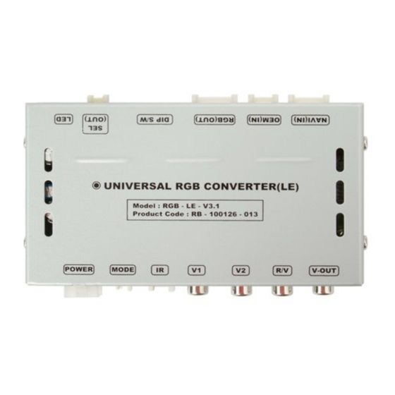
Page 6: Exterior
1.4 Exterior ⑬ ⑫ ⑪ ⑩ ⑨ ⑧ Dimension Horizontal length 129mm Vertical length 75mm Height 21mm ⑬ ⑫ ⑪ ⑩ ⑨ ⑧ ① POWER connector ② MODE connector for external button ③ IR-sensor connector ④ CVBS input V1 ⑤ CVBS input V2 ⑥... -
Page 7: Dip Switch
2.1 DIP switch #PIN Function DIP S/W selection ON : Deactivated RGB INPUT OFF: Activated ON : Deactivated CVBS1 INPUT OFF: Activated ON : Deactivated CVBS2 INPUT OFF: Activated SET OFF ON : Skipping OEM picture OEM picture OFF: OEM activated (normal use) * Caution ON : Non-Interlace INTERLACE*... -
Page 8: Remote Controller
2.2 Remote controller Function POWER & PIP No function MENU No function Making a selection ▲ Brightness higher ▼ Brightness lower ◀ Color lower ▶ Color higher SIZE : 85 * 40 * 8 (mm) -
Page 9: Power Cable Wiring Diagram
2.3 Power cable wiring diagram ⑥ ⑤ ④ FILTER & FUSE BOX ③ ② ① ① GND (black) ② N.C. ③ FM antenna ④ N.C. ⑤ ACC in +12V(red) ⑥ R-gear in +12V(gray) Blue FM antenna Orange N.C. Gray Black Blue 990mm Orange... -
Page 10: Installation
Cautions on installation Ignition key should be taken off before starting installation, interface power connection must be the last step in installation. Power cable should be separated when connecting interface. Should be no any electronic devices or magnetic pole around installation place. ... - Page 11 3.2 Installation diagram Control Box ※ Please make sure that Original the installation should be carefully conducted to avoid from the damage of a monitor B G R by ESD(Electrostatic R G B discharge) and misalignment while connecting the Offered module of a monitor with cables.
- Page 12 3.3 Installation 1. Connect sub-board to head unit. SUB Board Offered cable PORSCHE Board Connect offered FFC cable to sub- board.(LCD-IN (BOTTOM)) Offered cable...
- Page 13 3.3 Installation 2. Connect Original FFC cable to sub-board. LCD Original FFC cable Original FFC cable Connect Original FFC cable to sub-board.(LCD-OUT(BOTTOM)) Original FFC cable...
-
Page 14: Troubleshooting
Troubleshooting Q. I can not switch A/V sources. A. Check IR or Ground cable connection. Check LED lamps in the interface, if it is not on, check power cable. Q. All I got on the screen is black. A. Check second LED lamp of the interface is on, if not, check A/V sources connected are working well. (Second lamp indicates AV sources connected works well.) Check interface connection has been done well.
Need help?
Do you have a question about the RGB-LE-V3.1 and is the answer not in the manual?
Questions and answers