Table of Contents
Advertisement
Quick Links
Advertisement
Table of Contents

Summary of Contents for CTC Union IFC-CCF40
- Page 1 Quick Installation Guide IFC-CCF40 4 Channel Binary Transducer sales@ctcu.com...
- Page 2 8F, No. 60 Zhouzi St., Neihu, Taipei 114, Taiwan T +886-2-26591021 F +886-2-26590237 E sales@ctcu.com H www.ctcu.com 2020 CTC Union Technologies Co., LTD. All trademarks are the property of their respective owners. Technical information in this document is subject to change without notice.
- Page 3 CTC Union Technologies makes no warranty, representation, or guarantee regarding the suitability of its products for any particular purpose, nor does CTC Union assume any liability arising out of the application or use of any product and specifically disclaims any and all liability, including without limitation any consequential or incidental damages.
-
Page 4: Table Of Contents
Table of Contents Introduction .................. 5 Package List ................. 5 Features ..................5 Specifications ................6 ....................... 6 NPUT ......................6 UTPUT ....................... 6 IBER PTIC ......................7 OWER ...................... 7 ECHANICAL ....................7 NVIRONMENTAL ....................7 ERTIFICATIONS MTBF (MIL-HDBK-217) ..................7 Panels ................... -
Page 5: Introduction
Introduction IFC-CCF40 is a 4 channel bidirectional binary signal transducer that converts binary signals with a wide range input and transmits signals over fiber to a similar remote device. The transducers are designed for switchgear applications that require interference-free transfer of signals over fiber optic cables. -
Page 6: Specifications
Specifications Input 4 channel isolated binary input (BI-1, BI-2, BI-3, BI-4) Wide range input voltage (0~250VDC) Input threshold: 18V or 70V (Selectable via DIP switch) Maximum 2.5mA (per input channel) Removable terminal block connector Output ... -
Page 7: Power
Power AC or DC wide range input power 60~300VDC or 60~264VAC input range Support power input reverse polarity protection Removable terminal block connector Consumption: 3.6W Mechanical Water & Dust Proof: Rugged metal IP40 Protection ... -
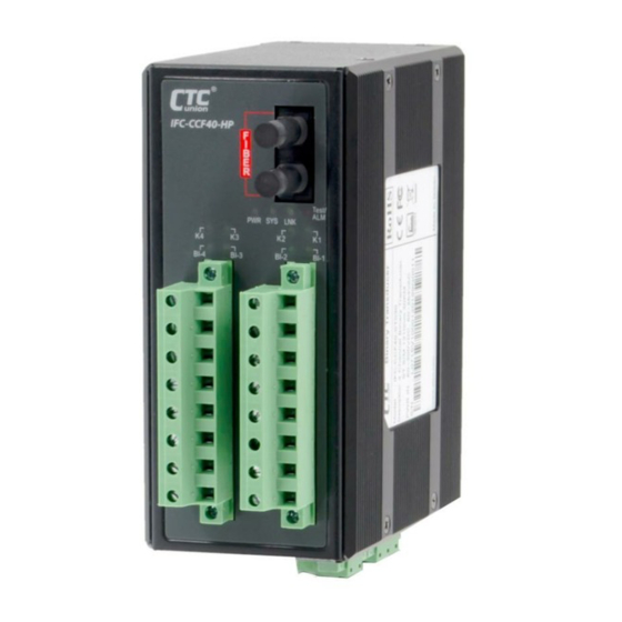
Page 8: Panels
Panels Figure 3. Bottom Panel Figure 2. Front Panel Description Two terminal blocks for 4 sets of binary inputs (BI-1, BI-2, BI-3, BI-4) & outputs (K-1, K-2, K-3, K-4) Fixed fiber connector LED indicators Grounding connector DIP Switch Alarm relay terminal block Power &... -
Page 9: Earth Ground Connection
Earth Ground Connection An earth ground connector is provided on the bottom panel with an earth ground sign next to it. Grounding the device can help to release leakage of electricity to the earth safely so as to reduce injuries from electromagnetic interference (EMI). -
Page 10: Recommended Power, Alarm, Ground Wiring Scheme
Recommended Power, Alarm, Ground Wiring Scheme DC / AC Power Connection Removable terminal blocks on the top panel provides both power and alarm connections. The left terminal block is for power connection. Power can be provided through the DC or AC input. See the figure below for example. -
Page 11: Led Indicators
LED Indicators Color Status Definition Power is connected and up. During firmware upgrade. (0.1s On & Green Flash 0.1s Off) (Power) Device is disabled. (1s On & 4s Off) Power is not connected. Normal operation. Green (System) System errors. Fiber link is up and syncs. Link is up but loses synchronization. -
Page 12: Dip Switch
DIP Switch Function Status Description BI-1 & BI-2 BI-1 & BI-2 binary inputs are over 18V binary input pick-up OFF* BI-1 & BI-2 binary inputs are over 70V threshold BI-3 & BI-4 BI-3 & BI-4 binary inputs are over 18V binary input pick-up OFF*... -
Page 13: Application
Application IFC-CCF40 can provide 4 binary inputs (BI-1, BI-2, BI-3, BI-4) and outputs (K-1, K-2, K-3, K-4). In the following example, BI-1 connectors receive input signals and then send signals via fiber optic to the remote K-1 output. The remote device reacts depending on signals received. -
Page 14: Installation
Figure 11. DIN Rail Figure 12. Wall Mount IFC-CCF40 with DIN Rail bracket has a steel spring in the upper rail of the bracket. This spring is compressed for mounting and un-mounting by applying downward force. Figure 13. Mounting... - Page 15 Version Date Description 2020/3/31 Use new document format. Change model name (remove HP). (VER. 20200727 Revise product photo. UNCHANGED)
Need help?
Do you have a question about the IFC-CCF40 and is the answer not in the manual?
Questions and answers