Table of Contents
Advertisement
Quick Links
UPB Universal Dimming Transceiver
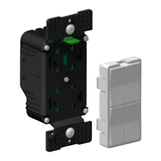
Model SW-2 shown with actuator faceplate
(sold separately)
Provides ON/OFF and dimming control for:
•
Incandescent lighting
•
Magnetic low-voltage lighting
•
Halogen lighting
IMPORTANT!
Read This Before Installing!
•
This incandescent dimmer
FLUORESCENT, ELECTRONIC LOW-VOLTAGE or METAL
HALIDE
lighting, unless specifically allowed by the lighting
manufacturer.
Please see instructions
for ON/OFF operation with these types of lighting.
•
DO NOT WIRE HOT!
Permanent damage may result. Improper
installation voids the warranty.
FUNCTION
The SW-2 UPB Universal Dimming Transceiver allows remote control of
permanently-installed new or existing lighting fixtures, lamps and other
electrical devices. Each unit has one rocker switch that directly controls a
load up to 900W (see Rating Table in this document). Incandescent
lamps can be turned ON or OFF, and can also be dimmed and
brightened. The SW-2 can be configured to turn other types of non-
dimmable loads ON and OFF. Actuator faceplates (model series SW-1x,
SW-2x, SW-3x, SW-4x, WC-4x, WC-5x and WC-8x) are fully
interchangeable on the SW-2 base. All switch actuators act as
transmitters that can communicate with other UPB devices, either
individually or collectively for lighting scenes.
IMPORTANT SAFETY INSTRUCTIONS
When using electrical products, basic safety precautions should always
be followed, including the following:
1.
READ AND FOLLOW ALL SAFETY INSTRUCTIONS.
2.
REMOVE YELLOW "INSTALL WITH CARE" LABEL BEFORE
INSTALLING.
3.
Installation should be performed by a qualified electrician.
4.
Keep away from water. If product comes into contact with water or
other liquid, unplug immediately.
5.
Never use products that have been dropped or damaged.
6.
Do not use this product outdoors.
7.
Do not use this product for other than its intended use.
8.
Do not connect multiple lamps that, when combined, exceed the
maximum load rating of the product, de-rated for multi-gang boxes
(see table in this document).
cannot be used to dim
to configure this product
9.
Do not install in areas that can exceed 120°F (e.g., in an attic).
10. To avoid the risk of overheating and possible damage to other
equipment, do not install to control a receptacle.
11. Do not cover the product with cloth, paper or any material when in
use.
12.
SAVE THESE INSTRUCTIONS.
INSTALLATION
The SW-2 UPB Universal Dimming Transceiver is designed to be installed
in a junction box that is wired to a readily accessible over-current
protection device in the building wiring per NEC and CEC electrical codes.
CAUTION:
The default switch configuration operates as a dimmer
for incandescent lamps. It will also dim magnetic low-voltage and
halogen lamps. To control fluorescent, electronic low-voltage or metal
halide lamps, or motor-operated appliances, transformer-supplied
appliances or fans, the switch must be reconfigured for ON/OFF
Operation (no dimming) prior to use. Refer to the section on
CAUTION: DO NOT WIRE THIS DEVICE WITH POWER
CONNECTED. Injury or permanent damage to the device
may result. Improper installation voids the product warranty.
1.
Locate the existing wall switch for the lighting to be controlled. Note
that the lamp rating (or the combined rating of multiple connected
lamps) must not exceed the values shown in the following table:
1
600W
Number
of J-box
2
800W
Gangs
3+
900W
2.
Disconnect power at the circuit breaker. (NOTE: You MUST do this.
Wiring this switch "Hot" will damage the switch and void its warranty.)
3.
Remove the existing wall switch hardware. Disconnect the wires to
the switch.
4.
Remove the yellow "INSTALL WITH CARE" label, if present.
5.
Using a wire nut, connect the black (Line) wire of the switch to the
black (Line) power wire.
6.
Using a wire nut, connect all white (Neutral) wires together.
7.
Using a wire nut, connect the brown (load output) wire of the SW-2 to
the black wire of the device to be controlled.
8.
IF THIS IS TO BE A 3- OR MORE-WAY INSTALLATION, MAKE
SURE YOU INSTALL AN SW-3 AT ALL 3-WAY LOCATIONS.
CONNECTING THIS SWITCH TO A MANUAL 3-WAY SWITCH
WILL DAMAGE THE SWITCH AND VOID THE WARRANTY. Use a
wire nut to connect the brown/white wire to the traveler wire that
extends to the remote switch. If there is a second remote and a
second traveler, use a wire nut to connect the red/white traveler to
the wire that extends to the second remote switch location. See
below for remote switch installation.
9.
Cap off any unused wires to prevent shorting.
10. Mount the switch inside the J-box using captive screws. DO NOT
OVER TIGHTEN THE SCREWS.
11. Reconnect power at the circuit breaker.
13882 E Grand Ave, Aurora CO 80015-1152 USA
Technical Support: www.webmtn.com or 303-627-1856
Model SW-2
Number of Load
Dimmers in J-box
1
2
3+
--
--
500W
--
700W
500W
Web Mountain Technologies
Revised: May 22, 2007
Advertisement
Table of Contents

Summary of Contents for Web Mountain Technologies SW-2
- Page 1 UPB devices, either individually or collectively for lighting scenes. Using a wire nut, connect the brown (load output) wire of the SW-2 to the black wire of the device to be controlled. IMPORTANT SAFETY INSTRUCTIONS...
- Page 2 SETUP MODE Hold the rocker faceplate assembly so that the clear plastic light pipe When configuring a UPB system, it is often necessary to place the SW-2 (LED) on the switch fits nicely into the recess on the top of the in SETUP mode in order to initiate self-identification on the powerline.
- Page 3 UPB Universal Dimming Transceiver Model SW-2 Web Mountain Technologies 13882 E Grand Ave, Aurora CO 80015-1152 USA Technical Support: www.webmtn.com or 303-627-1856 Revised: October 13, 2005...
- Page 4 BLUE. Tap the actuator twice again to exit SETUP configuration software. mode. To create a scene for one of the SW-2 actuators, set all scene Network Name “Network 1” devices to the desired light levels and then place them in SETUP Room Name “New Room Name”...
Need help?
Do you have a question about the SW-2 and is the answer not in the manual?
Questions and answers