Advertisement
Table of Contents
- 1 Table of Contents
- 2 TP-CU3-ZD and TP-CU3 Content
- 3 TP-CU3-ZD and TP-CU3 Overview
- 4 Step 1 - Rack Mount Tap
- 5 Step 2 - Connect AC Power
- 6 Connect DC Power
- 7 Step 3 - Configure the DIP Switches
- 8 Step 4 - Connect to the Network
- 9 Step 5 - Connect to the Monitoring Devices
- 10 Support
- Download this manual
Advertisement
Table of Contents

Summary of Contents for IXIA TP-CU3-ZD
- Page 1 Quick Install Guide TP-CU3-ZD, -DC Gig Zero Delay TP-CU3, -DC 10/100/1000BaseT Tap 913-2114-01 Rev B 1/15...
- Page 2 PLEASE READ THESE LEGAL NOTICES CAREFULLY. Trademarks and Copyrights Net Optics is a registered trademark of Net Optics, Inc. By using the TP-CU3 and TP-CU3-ZD taps, you agree to the terms and conditions of usage set forth by Ixia. Copyright © 2005-2015 Net Optics, Inc. with modifications Copyright © 2015 Ixia. All rights reserved.
-
Page 3: Table Of Contents
Contents TP-CU3-ZD and TP-CU3 Content TP-CU3-ZD and TP-CU3 Overview Step 1 - Rack Mount Tap Step 2 - Connect AC Power Connect DC Power Step 3 - Configure the DIP Switches Step 4 - Connect to the Network Step 5 - Connect to the Monitoring Devices... -
Page 4: Tp-Cu3-Zd And Tp-Cu3 Content
TP-CU3-ZD and TP-CU3 Content This guide provides the initial steps to set up and configure the following Tap models: • TP-CU3-ZD 10/100/1000 Tap with Zero Delay • TP-CU3-ZD-DC 10/100/1000 Tap with Zero Delay, -48V DC power • TP-CU3 10/100/1000 Tap • TP-CU3-DC 10/100/1000 Tap, -48V DC power Carefully unpack the Tap and check for damaged or missing parts. -
Page 5: Tp-Cu3-Zd And Tp-Cu3 Overview
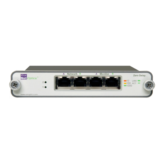
LEDs Network Monitor Zero Delay Zero Delay ® LINK 1000 www.netoptics.com Figure 1 - Front Panel, Gig Zero Delay Taps (TP-CU3-ZD, -DC) Power Network A & B Monitor A & B LEDs Full Duplex Tap Full Duplex Tap ® LINK... - Page 6 Figure 3 - Rear Panel AC (external transformer “brick”) power models DIP Switch Terminal Block Terminal Block on side For use with -48 only Figure 4 Rear Panel DC power model TP-CU3-DC DIP Switch Terminal Blocks For use with -48 only Figure 5- Rear Panel DC power model TP-CU3-ZD-DC...
-
Page 7: Step 1 - Rack Mount Tap
Step 1 Rack Mount Tap If you ordered the rack mounting panel, do the following: Remove the panel and screws from the shipping bag. Screw the panel onto the rack. Slide the switches in place in the rack. See Figure 6. See Figure 7 if you ordered the 12-Slot version. - Page 8 Figure 7- Tall 12-Slot Version...
-
Page 9: Step 2 - Connect Ac Power
Step 2 Connect AC Power Ensure the Tap is grounded before connecting power. Do the following to connect and apply power to the AC powered tap: Plug one of the supplied power cords to a power connector located at the rear of the chassis. -
Page 10: Connect Dc Power
Model TP-CU3-ZD-DC has a two-piece, screw-type terminal blocks for DC power. You can unplug half of the terminal block for convenience when connecting the power wires. -
Page 11: Step 3 - Configure The Dip Switches
Step 3 Configure the DIP Switches The 8-position DIP switch located on the rear panel or on the side of the device sets the communication parameters and battery connection as specified in the following table. Note: The settings apply to all ports on the Tap (except for Switch 1, Link Fault Detect, which applies only to the Network Ports). - Page 12 Switch Position Description Link Fault Detect (LFD) is active on the Network Ports. Link Fault Detect (LFD) is inactive on the Network Ports. See following table All ports are in Full-duplex mode. All ports are in Half-duplex. If switch 2 is ON, this switch is ignored Reserved Up position.
- Page 13 IMPORTANT NOTES: • The Tap is shipped with switches 1 and 2 in the ON position (LFD and Auto- negotiation active). • If you are using a fixed-speed setting, all devices connected to the Tap should also be set to that same speed. Furthermore, you should set only one speed switch to ON (up position).
-
Page 14: Step 4 - Connect To The Network
Step 4 Connect to the Network To connect the Tap to the Network: Connect Network Port A to the appropriate switch, server or router using one of the supplied purple CAT5e cables. Connect Network Port B to the appropriate switch, server or router using one of the supplied purple CAT5e cables. -
Page 15: Step 5 - Connect To The Monitoring Devices
Step 5 Connect to the Monitoring Devices To connect the Tap to the Monitoring device: Connect Monitor Port A to the appropriate port on the monitoring device using one of the supplied purple CAT5e cables. Connect Monitor Port B to the appropriate port on the monitoring device using one of the supplied purple CAT5e cables. -
Page 16: Support
Support If you have questions while your product is under warranty or you are enrolled in a support plan, please contact one of Ixia’s Technical Assistance Centers (TACs) by phone or e-mail. +1 818 595 2599 E-mail: support@ixiacom.com EMEA: +40 21 3015699 E-mail: support-emea@ixiacom.com...
Need help?
Do you have a question about the TP-CU3-ZD and is the answer not in the manual?
Questions and answers