
Summary of Contents for Caen RFID RA0002
- Page 1 RA0002 Digital I/O Interface Unit Technical Information Manual Revision n. 01 Authorized Reseller: RFID4UStore www.rfid4ustore.com 22/10/2013 1-408-739-3500 sales@rfid4ustore.com...
-
Page 2: Scope Of Manual
All you need to start using your module in a few clicks! Scope of Manual The goal of this manual is to provide the basic information to work with the RA0002 Digital I/O Interface Unit. Change Document Record Date... -
Page 3: Table Of Contents
Example n.1 ..............................19 Example n.2 ..............................21 Connect an Alarm Sounder to RA0002 ........................22 Connect a Led Signal Tower to RA0002 ........................24 How to Use Relay Output ............................26 RA0002 Technical Specifications ........................27 Technical Specifications Table ..........................28 External Connections .............................. -
Page 4: List Of Tables
Fig. 4.2: R0002 Front Panel LEDs ................................32 Fig. 4.3: RA0002 Mechanical Drawings ..............................33 List of Tables Tab. 2.1: Correspondence between the DB15 GPI/O and RA0002 GPI/O ....................9 Tab. 2.2: Startup GPI/O configuration ..............................11 Tab. 4.1: RA0002 Technical Specifications .............................28 Tab. 4.2: GPIO DB15 socket connector pinout ............................29 Tab. -
Page 5: Introduction
1 Introduction This Chapter gives general information about the RA0002 Digital I/O Interface Unit. It contains these topics: General Information Ordering Options Accessories Installation Notice RA0002 - Technical Information Manual... -
Page 6: General Information
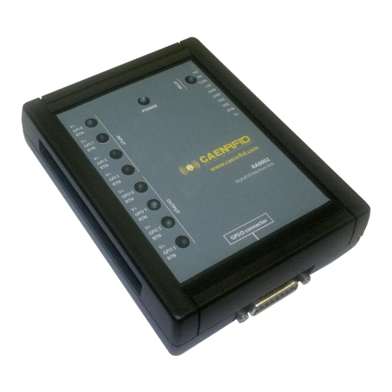
General Information The CAEN RFID RA0002 Digital I/O Interface Unit provides an easily accessible interface to the CAEN RFID readers’ digital inputs and outputs, in order to connect external devices such as motion sensors, lightstacks and audible alarms. The RA0002 GPIO connector is dedicated for the... -
Page 7: Installation Notice
Fig. 1.2: RA0002 Wall Mounting To hang the RA0002 on the wall, fix the hooks to the wall using 4 rawlplugs (ø 3 mm) (not included) + screws or, if you want to hang the RA0002 on a wood panelling, fix the hooks to the wall just using 4 screws. -
Page 8: Ra0002 Functional Description
2 RA0002 Functional Description This Chapter gives information about the RA0002 Digital I/O Interface Unit functional aspects. It contains these topics: General Description Power Supply Startup Input Electrical Description Output Electrical Description Safety Output System ... -
Page 9: General Description
Tab. 2.1: Correspondence between the DB15 GPI/O and RA0002 GPI/O In CAEN RFID readers each GPI/O channel can work both as an input and as an output, while in the RA0002 there are 4 input dedicated channels, 4 output dedicated channels and an output channel that drives a SPDT relay. -
Page 10: Power Supply
The input power and ground are also shown on the RA0002 device on terminals VDC and GND. Fig. 2.1: RA0002: power supply through DB15 connector When the RA0002 module is attached both to the Ion reader and to an external power supply, the following condition must be fulfilled: RA0002 Power Supply ≥... -
Page 11: Startup
Warning: During the boot process, a device connected to the RA0002 outputs may have particular behaviour: for example, an alarm sounder connected to RA0002 (like in the example n.1 of Connect an Alarm Sounder to RA0002 pag. 22) will be active and sound during the boot process. If you want it to be turned off during the boot process simply connect the alarm sounder to GPO2 or GPO3 or connect the alarm sounder like in the example n.2 of Connect an Alarm... -
Page 12: Input Electrical Description
Input Electrical Description The following diagram shows the equivalent schematics of the input stage of the RA0002 module, i.e GPI0. RA0002 module Fig. 2.3: Input electrical diagram The terminals V +, GPI0, RTN are the card’s interface toward the external devices. -
Page 13: Isolated Input Interface
Isolated input interface In the following example, an external isolated power supply is used to enable the GPI/O via the command given by the switch. RA0002 module Fig. 2.5: Isolated input interface RA0002 - Technical Information Manual... -
Page 14: Output Electrical Description
Output Electrical Description The following diagram shows the equivalent schematics of the output stage of the RA0002 module, i.e GPO0. RA0002 module Fig. 2.6: Output electrical diagram The terminals V +, 0 GPO, RTN are the card’s interface toward the external devices. -
Page 15: Switching N Mos Using Reader Power
Fig. 2.9: Switching P mos using external power It is the same configuration of the example Switching P mos using reader power pag. 14, but in this case the load is powered from an external source. RA0002 - Technical Information Manual... -
Page 16: Safety Output System
The output current of 4 outputs GPO0, GPO1, GPO2, GPO3 is limited by 4 resettable fuses (0.75 A). For the fuses response time, see the following figure: Fig. 2.10: Response time of resettable fuse The fuse properly restores its functionality once the current returns below the threshold level. RA0002 - Technical Information Manual... -
Page 17: Using Ion R4300P Gpio Interface
Using Ion R4300P GPIO Interface This paragraph describes how to manage the GPI/O of the Ion R4300P reader. The Ion R4300P reader has 13 general purpose input and output (GPIO) interfaces, but to control RA0002 you need only 9 signal. -
Page 18: Connecting The Ra0002
3 Connecting the RA0002 This Chapter gives some examples of usage of the RA0002 Digital I/O Interface Unit. It contains these topics: Connect a Photo-Electric Sensor to RA0002 Connect an Alarm Sounder to RA0002 Connect a Led Signal Tower to RA0002 ... -
Page 19: Connect A Photo-Electric Sensor To Ra0002
Relay common 24 poles connector V+ GPI0 RTN V+ GPI1 RTN V+ GPI2 RTN When the RA0002 module receive a valid input from the photo-elettric sensor , the connected GPI enables low is correspondent gpi/o. RA0002 - Technical Information Manual... - Page 20 RA0002 module receives a valid input from the When the RA0002 module receive a valid input from the photo-elettric sensor , the connected GPI enables low is photo-electric sensor, the connected GPI enables its correspondent GPI/O to low level.
-
Page 21: Example N.2
V+ GPI1 RTN V+ GPI2 RTN For example, using CAEN RFID Easy Controller software, when the RA0002 module receives a valid input from the photo-electric sensor, the connected GPI enables its correspondent GPI/O to low level. RA0002 - Technical Information Manual... -
Page 22: Example N.1
GPO 1 GPO 2 Example n.1: using CAEN RFID Easy Controller software, when you enable low the right GPI/O from the R4300P, the RA0002 module receives a valid output and power up the alarm sounder. RA0002 - Technical Information Manual... - Page 23 Example n.2: if you want to work with a positive logic, you have to connect the sounder as illustrated in the pictures below. When you enable high the right GPI/O from the R4300P, the RA0002 module receives a valid output and powers up the alarm sounder.
-
Page 24: Connect A Led Signal Tower To Ra0002
Connect a Led Signal Tower to RA0002 RA0002 is powered by R4300P Db15 connector R4300P RA0002 Led signal tower model – WERMA 69300055 10 poles connector +5V COM yellow 24 poles connector green V+ GPO 0 RTN GPO 1 GPO 2... - Page 25 CAEN RFID Easy Controller software, when you enable low the right GPI/O from the R4300P, the RA0002 module receives a valid output and power up the led signal tower. In this setup all the 3 lights are on. Note: In case of shared ground, like in the led signal tower case, we can work only in negative logic (active low signal).
-
Page 26: How To Use Relay Output
For example, using CAEN RFID Easy Controller software, when you enable low the GPI/O 8 from the R4300P, the RA0002 module receives a valid output and switch the relay to the Normally Open (NO) contact. RA0002 - Technical Information Manual... -
Page 27: Ra0002 Technical Specifications
4 RA0002 Technical Specifications This Chapter describes the technical specifications of the RA0002 Digital I/O Interface Unit. It contains these topics: Technical Specifications Table External Connections Front Panel LEDs Mechanical Drawings RA0002 - Technical Information Manual... -
Page 28: Technical Specifications Table
User interface Yellow LED: selected GPI/O information IP rating IP30 Operating Temperature -20 to 60 °C Humidity 5 to 95% (on-condensing) Dimensions (W)100,5 x (L)131 x (H)34,4 mm Weight 200 g Tab. 4.1: RA0002 Technical Specifications RA0002 - Technical Information Manual... -
Page 29: External Connections
External shell (connected to Ground) Tab. 4.2: GPIO DB15 socket connector pinout Fig. 4.1: GPIO DB15 socket connector pinout Warning: avoid connecting the DC_BYPASS signal to any of GPIO pins, otherwise the reader can be permanently damaged. RA0002 - Technical Information Manual... -
Page 30: Ra0002 Power Connector
RA0002 power connector Note: The RA0002 power connector is the same connector of the Ion R4300P reader. 10-pin terminal block with quick coupling for power and address signals Pin # Pin name Range 36 Vdc max 9 – 36 Vdc 9 –... -
Page 31: 24-Pin Terminal Block With Quick Coupling For Power And Address Signals
Push pull ( 0 ÷ 500 mA ) 36 Vdc max GPO2 Output Push pull ( 0 ÷ 500 mA ) 36 Vdc max GPO3 Output Push pull ( 0 ÷ 500 mA ) Tab. 4.4: 24-pin terminal block table RA0002 - Technical Information Manual... -
Page 32: Front Panel Leds
GPO0 activeted Yellow LED GPO1 GPO1 activeted Yellow LED GPO2 GPO2 activeted Yellow LED GPO3 GPO3 activeted Yellow LED RELAY NC contact Yellow LED Tab. 4.5: R0002 Front Panel LEDs Fig. 4.2: R0002 Front Panel LEDs RA0002 - Technical Information Manual... -
Page 33: Mechanical Drawings
Mechanical Drawings The mechanical drawings of RA0002 are shown in the figure below. All dimensions are in millimeters. 3 4.4 3 4.4 3 7.9 3 7.9 1 3 2.0 1 3 2.0 64.0 64.0 3 9.5 3 9.5 1 00.5 1 00.5...
Need help?
Do you have a question about the RA0002 and is the answer not in the manual?
Questions and answers