Table of Contents
Advertisement
Advertisement
Table of Contents

Summary of Contents for Strässle & Co DT100 C
- Page 1 Operating and safety instructions vacuum system DT100 C Strässle & Co. Medizintechnik GmbH Primelweg 5 D-72461 Albstadt Tel.: +49 (0)7432 - 220186 Fax: +49 (0)7432 - 220189 Email: info@straessle-co.de www.straessle-co.de Item # 1000.536 issue V18.3E from 01.07.2019...
- Page 2 Device symbols Follow instructions for use This part falls under classification BF This part falls under classification CF with defibrillation protection This part falls under classification BF with defibrillation protection ON Power switch: Power on Remote control: Switch vacuum system to stand-by mode and release vacuum OFF Power switch: Power off...
-
Page 3: Table Of Contents
TABLE OF CONTENTS DT100 General description Components Construction and function of the vacuum electrodes Construction and function of the delta distributor Construction and function of the support arm Construction and function of the vacuum unit Construction and function of the control unit Installation Installation of the support arm clamping device Connecting the vacuum unit... - Page 4 1. DT100 vacuum system The DT100 vacuum system is a medical product according to guideline 93/42/EWG. It is designed for operation with common ECG devices and offers improved safe ECG diagnostics combined with increased economical efficiency. The DT100 vacuum system suits for ECGs in rest as well as under stress test. Owing to the secure fixing of the electrodes it is especially advantageous in ergometry.
-
Page 5: Components
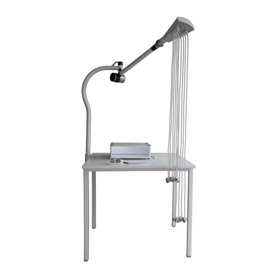
2. Components delta distributor support arm Item # 3000-170 electrode cables (application part) Item # 4000-002 electrode 1m Item # 4000-004 electrode 1,3m Item # 2000-159 code plate set 2.5 control unit Item # 3000-156 2.4 vacuum unit Item # 3000-201 Item # 3000-202 accumulator battery version issue V18.3E from 01.07.2019... -
Page 6: Installation
Electrode cables (application part) Ten electrode cables, that are R, L, N, F and C1 to C6, constitute the adaptation unit. A specially designed combined electrode head, self-locking and equipped with a silver/silver-chloride electrode, opens and adheres to the patient's body on slight finger pressure. Delta distributor The so-called delta distributor, the topmost part of the support arm, holds the electrodes in such a way that they cannot be connected improperly. -
Page 7: Connecting The Vacuum Unit
Fasten screw in order to prevent Fasten screw until the tube from pivoting. the tube is securely (bores must match) fixed at the clamping device. 3.1.1 Connecting the patient cables to the ECG device Only CE marked devices may be connected [example] (see also operating instructions ECG) 3.2 Connect the vacuum unit... - Page 8 3.4.2 Position the support arm as desired Delta distributor Note: This is a stiff joint that´s impossible to rotate! Locking bolt To unlock, pull out the bolt. Now the arm can be pivoted horizontally. There are three positions to lock: left position, middle position, right position. Setting of the locking bolt (from year 2011) The locking bolt can elective be detended so that the boom does not snap in any pivot position.
- Page 9 3.4.3 Switch on the vacuum Press the I/O button Pressure level 1 LED to release the vacuum will turn on Select vacuum level The vacuum level can be changed by pressing the arrow keys at any time. The selected vacuum level will be displayed by light emitting diodes.
-
Page 10: Technical Appendix
4. Technical appendix General information The device is suitable for continuous operation. Integrated defibrillation protection protects subsequent devices. High-frequency fields and emissions may influence the quality of the ECG measurements. The DT100 ECG vacuum unit is provided with a CE label according to the guideline given by the Council on Medical Products 93/42 EWG and meets the basic requirements of Annex VII of the named guideline. -
Page 11: Cleaning And Disinfection Of The Vacuum Electrodes
Cleaning and disinfection of vacuum electrodes The surface of the vacuum electrodes must not be scratched or damaged. The surface cleaning is done by spraying the alcohol disinfectant after each use (and maybe cleaned with a cleaning cloth) For safe disinfectant to the manufacturer's instructions, especially the required exposure times, are observed. The number of cleaning cycles under operating conditions has no negative impact on durability. -
Page 12: Ecg Plug-In Cable
4.4.1 Chemical-thermal disinfection In the case of suspected contamination, the used vacuum lines should immediately be submitted to chemical-thermal disinfection. With it, the vacuum lines will be submitted to a validated process of exterior and interior cleaning/disinfection (for informations please ask the manufacturer). -
Page 13: Specifications
Specifications Medical product class I (93/42/EWG) Supply voltage 230V~ 50Hz Rated consumption 50VA Vacuum range 60hPa - 260hPa Protection class Protection type IP N4N0 Degree of protection BF (Supporting arm BF or CF defibrillation protected) ... -
Page 14: Safety Instructions
5. Safety instructions The device should be operated only with a functioning mains supply according to VDE 0100-710, or applicable regulations, respectively. The device is assigned to group 1 (medical equipment-ECG) according to VDE 0100-710. In order to avoid electrical shock hazard, the device should be connected only to a mains supply with a protective conductor. It should not be used with a mains supply with protective disconnector. - Page 15 Appendix to 3.4.2 Position the support arm as desired 3.4.2.1 versions of support arm (optional) support arm-CL part.-no. 3000-171 Assambly as described in paragraph 3.1 Locking bolt Note: This is a stiff joint that is impossible to rotate! support arm-CLW part.-no.
Need help?
Do you have a question about the DT100 C and is the answer not in the manual?
Questions and answers