Table of Contents
Advertisement
Quick Links
Advertisement
Table of Contents

Related Manuals for Advent Powerline APWL2012

Summary of Contents for Advent Powerline APWL2012
- Page 1 Powerline Starter Kit Instruction Manual APWL2012...
-
Page 2: Table Of Contents
CONTENTS System Requirements Unpacking Product Overview Connecting Mechanism 7 LED indicator 8 Physical Interface 9 Hardware Connection – Computer 10 Hardware Connection – Internet 11 Installing PowerLine Utility 15 Using the PowerLine Utility 15 Accessing the Configuration Settings 16 Status 17 Setting Local Device’s Network Name 18 Network 20 Renaming the Powerline Adaptor and Enter Password 22 Adding a Remote Powerline Adaptor 24 System... - Page 3 29 How To Use The Pair Buttons 29 Pairing (secure with 128-bit AES) 29 Setting Up a Powerline AV Network with the Pair Button 30 Creating a Powerline Network Using the Pair Buttons 30 Joining an Existing Powerline AV Network 31 Leaving an Existing Powerline AV Network 31 Resetting the Powerline AV Network 32 Hints And Tips 33 Safety 34 Product Specifications...
-
Page 4: System Requirements
Thank you for purchasing your new Advent Powerline Adaptor Kit. We recommend that you spend some time reading this instruction manual in order to fully understand all the operational features offered. Read all the safety instructions carefully before use and keep this instruction manual for future reference. The Advent 200Mbps Ethernet Powerline Adaptor offers the following features: > Extends your computer network to the whole house > Adds a previously-unassociated device to an existing connection SYSTEM REQUIREMENTS 1. -
Page 5: Unpacking
UNPACKING Remove all packaging from the unit. Retain the packaging. If you dispose of it please do so according to local regulations. The following items are included: Powerline Adaptor x 2 Ethernet (RJ-45) Cable x 2 P.N.: APWL2012-Ethernet Quick Start Guide CD-ROM P.N.: APWL2012-QSG P.N.: APWL2012-CD001... -
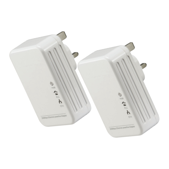
Page 6: Product Overview
PRODUCT OVERVIEW Power Indicator (PWR) Powerline Indicator (PLC) Ethernet Indicator (ETH) Pair Plug Pair Button Ethernet Port... -
Page 7: Connecting Mechanism
CONNECTING MECHANISM The Powerline Adaptors work in pairs; you need one Powerline Adaptor connected to the internet and also one Powerline Adaptor per computer you wish to connect to the network. Maximum distance between 2 x Powerline Adaptors is 300m, without obstructions. LED indicator The LED indicator displays information about the Powerline Adaptor’s status. Item Status Indication The Powerline Adaptor is off. Solidly lit The Powerline Adaptor is on. Power indicator The Powerline Adaptor is in power-saving Flashing (PWR) mode. -
Page 8: Physical Interface
Physical Interface There are 3 physical interfaces on this Powerline Adaptor. Item Usage / Description • 10/100Mbps UBS port Ethernet • Connects the Powerline Adaptor to a PC or broadband Port device with network cable • Connects the Powerline Adaptor to a 100V ~ 240V AC Plug power socket. • Secures a powerline network • Follow the steps below: 1. -
Page 9: Hardware Connection - Computer
Hardware Connection – Computer To connect a computer to the Powerline Adaptor, you must use an Ethernet (RJ-45) cable (included). Follow the steps below to connect a computer to the Powerline Adaptor. 1. Connect the provided Ethernet cable to your computer’s LAN port. 2. Connect the other end of the Ethernet cable to the Powerline Adaptor’s Ethernet port. 3. Plug the Powerline Adaptor into a wall socket next to the computer. Ensure the wall socket is turned ‘ON’. 4. Turn on your computer. PWR indicator and ETH indicator 5. -
Page 10: Hardware Connection - Internet
Hardware Connection – Internet To connect the Powerline Adaptor to your existing broadband service, follow the steps below: 1. Connect the Ethernet cable to an available Ethernet port of your ADSL Broadband Router. 2. Connect the other end of the Ethernet cable to the Powerline Adaptor’s Ethernet port. 3. Plug the Powerline Adaptor into a wall socket next to the computer. Ensure the wall socket is turned ‘ON’. Turn on your computer. PWR indicator, PLC indicator, and 4. Check and confirm that the ETH indicator on the Powerline Adaptor are ON. PLC indicator does not illuminate, please follow the routine 5. -
Page 11: Installing Powerline Utility
INSTALLING POWERLINE UTILITY Please verify that the following is correct before installing the provided software: Item Status If Status is Not Correct, then: Other Powerline None Uninstall, then restart the computer Adaptor(s) Other Encryption None Uninstall, then restart the computer Management Utilities Other Powerline Utilities None Uninstall, then restart the computer Ensure you have already installed WinPcap (4.11 or above) (not included) before installing the PowerLine Utiltiy. If not, a window will pop up for you to install WinPcap 4.1.1. 1. Insert the supplied Resource CD into a CD drive on the computer that is connected to your router. 2. - Page 12 3. Follow the prompts on the Installation Wizard Windows.
- Page 14 4. After installation, a shortcut to the “APWL2012” application icon will be automatically placed on the Windows desktop. ® APWL2012...
-
Page 15: Using The Powerline Utility
USING THE POWERLINE UTILITY After successfully installing the Powerline Adaptor hardware and software, you can set up or configure devices according to your needs. The Ethernet Powerline Adaptor Configuration Utility allows you to do the following: > Identify Powerline devices on the Powerline network > Measure data rate performance > Ensure privacy > Perform diagnostics through setting user-defined secure Powerline networks This procedure is only recommended for experienced users. -
Page 16: Status
Status The Status tab shows the information of the Powerline Adaptor that is connected to the current computer that is running the PowerLine Utility programme. In this window, you can also set the Network Name. MAC Address Show’s the Powerline Adaptor’s MAC address. Network Name Shows the current Network Name. You can change the Network Name by typing into the text box next to “Network Name”. The default name for the network name is HomePlugAV. Use Default (HomePlugAV) Check the box if you wish to use the default network name. Apply Click Apply to confirm the settings. Password Shows the current password of the Powerline Adaptor. Note the format of the password. -
Page 17: Setting Local Device's Network Name
Firmware Shows the current firmware version used by the Powerline Adaptor. Refresh Button Click the Refresh button to update the information. Setting Local Device’s Network Name Sets the local device’s network name. 1. Click the Status tab to display the Status window. 2. Enter a name for the current networking using 4-23 characters. 3. Click Apply to confirm the settings. If you want to use the default name (HomePlugAV) as your network name, check the “Use Default (HomePlugAV)”, then click the Apply button to confirm. -
Page 18: Network
Network The Network tab shows all the Powerline Adaptors found on the current logical network. Furthermore, you can change the Name of the listed Powerline Adaptors as well as add another device to the current network. PWR indicator Ensure all Powerline Adaptors are not in Powersave mode ( flashing). If so, power off/on. Type Shows the type of remote device found in the network (not the device currently connected to the computer in use). Name Shows the name of the remote device in the network. MAC Address Shows the MAC address of the remote device found in the network. - Page 19 Password On first use, this is blank. If a password has been set, this section will show the current password of the Powerline Adaptor. When creating a private network, or managing all devices, a password is required. To set the password, follow the steps below: 1. Select the target device listed in the window. 2. Click Modify. 3. Follow the prompts in the pop-up dialogue boxes to complete your password setting. > The password typically appears as an alphanumeric code, in groups of 4, separated by dashes and can be found on the back of the Adaptor, i.e., CNBT-OLEG-IPLK-YPGR. Rate (Mbps) Shows the current transmission rate of the Powerline Adaptor (not the maximum rate of 200Mbps). Option Change the corresponding Powerline Adaptor’s name and password by selecting the device and click the Modify button. Rescan Button Click the Rescan button to perform an immediate search of the Powerline Adaptor.
-
Page 20: Renaming The Powerline Adaptor And Enter Password
Renaming the Powerline Adaptor and Enter Password In this tab, you can: > Change the name of the remote adaptor(s). > Select the desired adaptor and change its password, so you can set the Network Name in the System configuration tab. To change the name of the remote adaptor(s) and enter its password, follow the steps below: 1. In the Network window, select the desired Powerline Adaptor. 2. Click the Modify button to display the dialogue window. - Page 21 3. Enter a new name or edit the name and enter the password (note the password format, which can be found on the rear of the adaptor, e.g., CNBT-OLEG-IPLK-YPGR). 4. Click the Save button to confirm. 5. Repeat Steps (1) to (4) for all Powerline Adaptors on your network. > It is not necessary to enter a password when renaming a device. > If using a password, enter it in UPPER CASE. > The password typically appears as an alphanumeric code, in groups of 4, separated by dashes and can be found on the back of the Adaptor, i.e., CNBT-OLEG-IPLK-YPGR.
-
Page 22: Adding A Remote Powerline Adaptor
Adding a Remote Powerline Adaptor You can add a remote Powerline Adaptor to your network that is not in the displayed list. It is recommended that you locate the passwords for all the Powerline Adaptors you wish to manage and add them to the local logical network by clicking Add. 1. In the Network window, click the Add button to display the dialogue box. - Page 23 2. Enter a name (default for new devices is HomeplugAV) and a password for the device. Click the Save button to confirm. 3. If problems are encountered, pair the new device as described in the section, “Hardware Connection – Internet”, then repeat the steps in the section, “Add a Remote Powerline Adaptor”. > The Powerline Adaptor must be present on the power grid in order to activate the set password and be added to the local network. > Please note the password format, enter it uppercase.
-
Page 24: System
System The System tab shows some basic settings of the Powerline Adaptor. In this tab, you can: > Upgrade the firmware to the latest version. > Reset the Powerline Adaptor’s settings to the factory defaults. > Configure all Adaptors’ network names. -
Page 25: Upgrade Firmware
Upgrade Firmware 1. In the System window, click the Upgrade Firmware button to display the dialogue box. NVM (Non-Volatile Memory) Used to upgrade the firmware. PIB (Parameter Information Block) This contains configuration values that establish: > Device network identity > General capabilities > Operational modes... -
Page 26: Resetting To Default
2. Download the firmware upgrade files and PIB from www.adventcomputers.co.uk. 3. Enter the file path for the NVM (Non-Volatile Memory) information, or click the button on the right and then select the appropriate files. 4. Enter the file path for the PIB information, or click the button on the right and then select the appropriate files. 5. - Page 27 Click the Reset All Devices button to reset all devices that appear in the Network configuration tab whose device’s password have been entered for the same logical network. A dialogue window will pop up to report the success of this operation.
-
Page 28: Setting All Devices' Network Name
Setting All Devices’ Network Name To change the logical network of all devices that appear on the Network configuration homepage whose device’s password had been entered for the same logical network. In the System window, enter the network name and then click the Set Network Name button to confirm. > If you want to use the default name (HomePlugAV) as your network name, check the “Use Default (HomePlugAV)”, then click the Set Network Name button to confirm. > Every Powerline Adaptor MUST have the same Network Name for connectivity to be established throughout your home. >... -
Page 29: How To Use The Pair Buttons
HOW TO USE THE PAIR BUTTONS Pairing (secure with 128-bit AES) The Homeplug AV standard uses 128-bit AES (Advanced Encryption Standard) to safely transmit data between Powerline Adaptors. For the Powerline Adaptors to communicate with each other they all need to use the same Network Membership Key (NMK). Otherwise, they cannot unscramble the encrypted data sent in the powerline network. The Pair button allows you to set up a secure powerline connection with other HomePlug AV compliant powerline devices which also support the Pair feature. -
Page 30: Creating A Powerline Network Using The Pair Buttons
Creating a Powerline Network Using the Pair Buttons 1. Press and hold the Pair button of Powerline Adaptor A for 3-8 PWR indicator will start flashing. seconds then release, the 2. Press and hold the Pair button of Powerline Adaptor B for 3-8 PWR indicator will start flashing. seconds then release, the The Pair buttons must be pressed within 2 minutes of each other. 3. -
Page 31: Leaving An Existing Powerline Av Network
1. Press and hold the Pair button on the Powerline Adaptor C for 3-8 PWR indicator will start flashing. seconds then release, the 2. Press and hold the Pair buttons on the Powerline Adaptor A and PWR indicator will start B for 3-8 seconds then release, the flashing. > Step 2 must be performed within 2 minutes of step 1. >... -
Page 32: Hints And Tips
HINTS AND TIPS Problems Solutions • Make sure that the Powerline Adaptor is properly plugged into a power outlet. • Make sure the power outlet is active by plugging another electric device into it. indicator does not light up. • Re-plug the Powerline Adaptor to the mains PWR indicator still fails to light socket. If the up, contact your local dealer for technical support. • Make sure that the Ethernet (RJ-45) cable is properly connected to the Powerline Adaptor’s Ethernet port. • Make sure that the other end of the Ethernet (RJ- 45) cable is properly connected to the computer LAN card or to your Cable/xDSL Ethernet port. -
Page 33: Safety
SAFETY 1. Do Not open this product or attempt to service this product, it may expose you to dangerous high voltage and other risks. 2. Do Not operate this product near water. 3. Do Not place or operate near or over radiator or heat register. 4. Do Not expose this product to dampness, dust or corrosive liquids. 5. Do Not connect this product and Disconnect from wall socket during a lightning or thunderstorm. 6. Do Not obstruct this product ventilation slots, as insufficient airflow may harm this product. 7. Do Not put anything on this product. 8. Plug directly into wall socket (100Vac~240Vac). Do Not use an extension cord between this product and the AC power source. 9. When plugging this product into wall socket, make sure that electrical socket is not damaged. 1 0. Place the connecting cables carefully so people won’t stumble or walk on it. -
Page 34: Product Specifications
PRODUCT SPECIFICATIONS Model Number APWL2012 Dimensions (L x W x H) 92 x 57 x 30 mm Operating Temperature 0°C~40°C (32°F~104°F) Storage Temperature -40°C~70°C (-40°F~158°F) Operating Humidity 10%~90% non-condensing Storage Humidity 5%~90% non-condensing Power Consumption MAX. 3.1W Frequency Band 1.8~30MHz Data Rate 200Mbps Security Support 128bit AES • Support max 6 stations conneted with each other... - Page 35 Windows is a registered trademark of Microsoft Corporation in the United States and other countries. ADVENT Powerline declares that the Powerline Kit complies with the essential requirements and other relevant provisions of Directive 1999/5/EC. This symbol on the product or in the instructions means that your electrical and electronic equipment should be disposed at the end of its life separately from your household waste. There are separate collection systems for recycling in the For more information, please contact the local authority or your retailer where you purchased the product.
Need help?
Do you have a question about the Powerline APWL2012 and is the answer not in the manual?
Questions and answers