Advertisement
Quick Links
Advertisement

Summary of Contents for XMark Fitness XM-7626.1
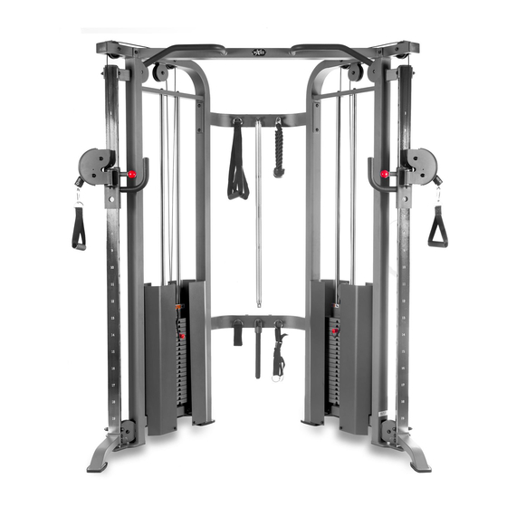
- Page 1 XM-7626.1 FUNCTIONAL TRAINER Owner’s Manual 10/20...
-
Page 2: Table Of Contents
Table Of Contents Important Safety Information Before You Start Assembly 5-16 Parts List Exploded View... -
Page 3: Important Safety Information
Important Safety Information Prior to assembly, remove components from the box and verify that all the listed parts were supplied. SAFETY INFORMATION WARNING! Before using this unit or starting any exercise program, consult your physician. This is especially important for persons over the age of 35 and/or persons with pre- existing health problems. -
Page 4: Before You Start
Before You Start THANK YOU for making this unit a part of your exercise program. XMark assur es the very best in value, appearance, durability and biomechanics. This manual will guide you through the assembly process. If at any time you are having trouble with the assembly or use of this product, then please contact us at service@xmarkfitness.com. -
Page 5: Assembly
Assembly... - Page 6 Assembly 2 or more people are required. This makes the process of assembly faster and safer. STEP 1: Connect Left Frame (#1) and the Right Frame (#2) with two Rear beam (#4) using: • 2 x Button Head Cap Screw (#55) •...
- Page 7 Assembly STEP 2: Connect Main Top Beam (#3) and the Left Frame (#1) and Right Frame (#2) using: • 4 x Button Head Cap Screw (#52) • 8 x Flat washer (#60) • 4 x Nylon lock nut (#64) Wrench Tighten the bolts before moving to the next step...
- Page 8 Assembly STEP 3: Slide Weight Bumpers (#37) onto Guide Rods (#19) and place into Left Frame (#1) Threaded end of Guide Rods should be on top. Slide 19 Weight Plates (#40) onto Guide Rods (#19) with pin slot facing inward. Slide Top Plate (#34) onto Guide Rods (#19) with pin slot facing inward.
- Page 9 Assembly STEP 4: Attach Left Slip Frame (#5) onto the Left Slip Tube (#13) - The holes on the Slip tubes will be facing the inside of the unit. Attach the Left Slip Tube (#13) and the Front Support Frame (#69) to the Left frame (#1) using: •...
- Page 10 Assembly STEP 5: Lower the threaded end of one Pulley Cable (#8) down the Left Frame (#1) Retrieve the threaded end of the Pulley Cable (#8) from the bottom of the Left Frame (#1) Attach the threaded end of the Pulley Cable (#8) to the Left Slip Frame (#5)
- Page 11 Assembly STEP 6: Attach two 4.5" Pulleys (#33) to the Left Frame (#1) using: • 2 x Button Head Cap Screw (#57) • 4 x Flat Washer (#60) • 2 x Nylon Lock Nut (#64) These pulleys go where the cable was routed in the STEP 5. The cable will route beneath the bottom 4.5"...
- Page 12 Assembly Cable Assembly Exploded View Cable Routing: Before the cable can be routed, the cable assembly will need to be temporaly disassembled. 1. Unscrew the Axel Bolt 2. Detach the Cable Adapter 3. Slide off the Cushion Cover 4. Remove the Protect Jacket Cable Assembly Parts List Ref # Description...
- Page 13 Complete cable routing as shown below Cable routes above the Frame. Not doing so can damage the cable. START Reassemble Cable Assembly: 1. Add the Protect Jacket 2. Slide on the Cushion Cover 3. Attach the Cable Adapter 4. Screw on the Axel Bolt...
- Page 14 Assembly STEP 10: Attach four Shroud Brackets (#12) to the Left Frame (#1) using: • 2 x Button Head Cap Screw (#53) • 4 x Flat Washer (#60) • 2 x Nylon Lock Nut (#64) Attach two Weight Shroud (#11) to the Left Frame (#1) using: •...
- Page 15 Weight Stack Sticker Placement The weight stack image below illustrates how the weight stack decals should be applied to the weight stack. Please note these decals should not be put on until the entire unit has been assembled and all bolts and nuts have been tightened. 200 LB Stack...
- Page 16 Apply to guide rods if friction occurs. Never put lubricant on the cables. Touch Up Paint: A small bottle of gray touch up paint is provided if you ever scratch your machine. Congratulations! You have completed the assembly of your new XM-7626.1.
-
Page 17: Parts List
Parts List XM-7626 Parts List Qt y Ref # Part # Description P00251 Frame, Left XM-7626 P00252 Frame, Right XM-7626 P00253 Beam, Main Top XM-7626 P00254 Beam, Rear XM-7626 P00255 Frame, Slip Left XM-7626 P00256 Frame, Slip Right XM-7626 P00257 Spacer, Pulley Longer XM-7626 P00258 Cable, Pulley XM-7626... -
Page 18: Exploded View
Exploded View... - Page 19 Customer Service: 1-800-719-4605...