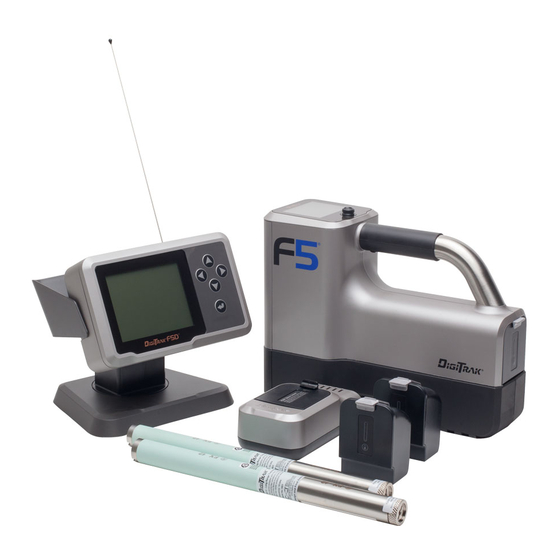
Summary of Contents for DCI DigiTrak FALCON F5 Sub-k Rebar
- Page 1 Supplement B Sub-k Rebar Transmitter ™ Full Scale Sensitive Pitch (FSSP) Frequency Optimizer Update and other recent updates dci@digital-control.com www.DigiTrak.com...
- Page 2 Patents Patent pending. Limited Warranty All products manufactured and sold by Digital Control Incorporated (DCI) are subject to the terms of a Limited Warranty. A copy of the Limited Warranty can also be obtained at www.DigiTrak.com. Important Notice All statements, technical information, and recommendations related to DCI products are based on information believed to be reliable.
-
Page 3: Table Of Contents
IGITAL ONTROL NCORPORATED Table of Contents Important Safety Instructions What is This Document For? Other Documents What's New Frequency Optimizer (FO) Selecting Sub-k™ Rebar Switching Bands Optimizing with Sub-k™ Rebar Full Scale Sensitive Pitch (FSSP) Surface Grade Compatible Transmitters Transmitter Current Draw Warning Changing Frequency Bands Updates to Manual Getting Started... - Page 4 IGITAL ONTROL NCORPORATED Supplement B for DigiTrak ® Falcon F5 ®...
-
Page 5: Important Safety Instructions
NCORPORATED Important Safety Instructions Always operate your DigiTrak locating system properly to obtain accurate depth, pitch, roll, and locate points. If you have any questions about the operation of the system, please contact DCI Customer Service for assistance. ® This document is a companion to your Falcon F5... -
Page 6: Frequency Optimizer (Fo)
IGITAL ONTROL NCORPORATED Frequency Optimizer (FO) The frequency optimizer now shows active interference in the two currently optimized bands as live graphs at the left of the FO screen. If you walk the intended bore path with the transmitter off and these levels remain low, the current bands may be performing well enough that you may choose to not scan and pair new frequency bands. -
Page 7: Selecting Sub-K™ Rebar
IGITAL ONTROL NCORPORATED Selecting Sub-k Rebar ™ On a Sub-k™ Rebar (FTR) transmitter, the receiver uses six frequency bands specifically intended for use in areas of high passive interference: Depth Bands Data Bands Band Number Range in kHz 0.33 – 0.40 0.40 –0.58 0.58 –... -
Page 8: Switching Bands
IGITAL ONTROL NCORPORATED Switching Bands Switch the transmitter between Up and Down bands pre- or mid-bore using any of the methods described in the Falcon F5 QSG or operator's manual. On the receiver, hold-toggle right at the Locate screen to open the Band Selection Menu, where you can switch between the optimized Up and Down bands and turn on fluid pressure monitoring. -
Page 9: Optimizing With Sub-K™ Rebar
IGITAL ONTROL NCORPORATED Optimizing with Sub-k Rebar ™ The frequency optimizer (FO) has a slightly different look when you use a Sub-k™ Rebar transmitter. In addition to the currently optimized FO bars at the left, the remaining bars show the active interference (noise) in just six low-frequency bands. -
Page 10: Full Scale Sensitive Pitch (Fssp)
IGITAL ONTROL NCORPORATED 10. Pair the transmitter by aligning the IR ports (the divot on the transmitter and the small round port in the upper center portion of the receiver front) and clicking the trigger. 11. After pairing, the transmitter defaults to using the Down band. Calibrate with the transmitter in a housing in both the Up and Down bands, then perform an AGR test as described in the Falcon F5 operator's manual. -
Page 11: Surface Grade
IGITAL ONTROL NCORPORATED While in FSSP mode, fluid pressure resolution decreases: Standard Resolution 0 – 75 1 psi 75 – 250 5 psi FSSP Resolution 0 – 50 5 psi 50 – 150 10 psi 150 – 250 20 psi Surface Grade Surface grade assists in determining the pitch of the surface terrain being drilled, which is useful when it is necessary to maintain a consistent drilling depth. -
Page 12: Compatible Transmitters
IGITAL ONTROL NCORPORATED Compatible Transmitters From the Main menu select System Information and toggle down to the third page to read which transmitters are compatible with your Falcon F5 receiver. If an iGPS module is properly connected, this page displays its serial number and software versions as shown. System Information Screen As of mid-2017, Falcon F5 system has its own 8-inch transmitter, the FTR5s. -
Page 13: Updates To Manual
IGITAL ONTROL NCORPORATED Updates to Manual Beyond the features already discussed in this document, this section addresses numerous updates and improvements to the current Falcon F5 Operator's Manual, including helpful tips on using certain features. They are marked as New, Helpful, Clarification, or Deleted. Please read these topics to learn the latest information about your locating system. -
Page 14: Datalog
IGITAL ONTROL NCORPORATED DataLog Left/Right Offset Helpful: Offset can be turned on or off and the distance between selected rods can be changed at any point along the bore path. Flags and Pins Clarification: Flags and Pin position relative to the rod number being recorded must be based on the Locate Line (LL), not a Front or Rear Locate Point (FLP, RLP). -
Page 15: Diagnostics
IGITAL ONTROL NCORPORATED Diagnostics New: The Perform Level Check feature now displays the numeric value of the surface grade. Knowing the surface grade is helpful for maintaining a consistent drilling depth. See Surface Grade on page 7. Locating Screens Depth Screen, Max Mode Helpful: During deep bores or around extreme interference conditions, the locating ball and/or locate line (LL) may not center properly in the box. -
Page 16: Transmitter Drill Head Requirements
IGITAL ONTROL NCORPORATED Transmitter Drill Head Requirements New: For 8" transmitters: 1. Battery cap 2. Slot position 3. Front end cap A. Slot length B. Distance C. Transmitter length A Minimum B Maximum 8" wideband transmitter 4.0" 1.0" 8" – End of Supplement – Supplement B for DigiTrak ®...


Need help?
Do you have a question about the DigiTrak FALCON F5 Sub-k Rebar and is the answer not in the manual?
Questions and answers