
Related Manuals for Rottler P69AHD

Summary of Contents for Rottler P69AHD
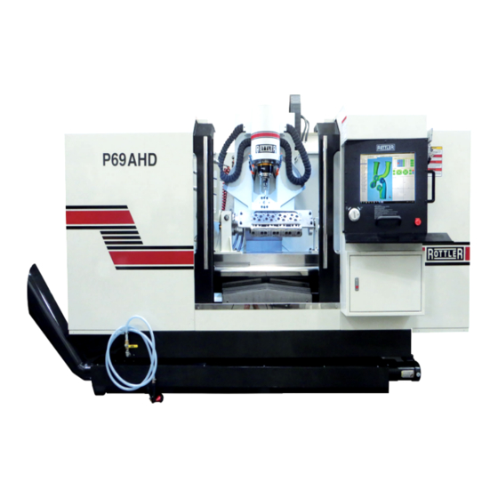
- Page 1 OPERATION AND MAINTENANCE MANUAL 8029 S 200th St. Kent, WA 98032 USA | www.rottlermfg.com | Ph: 253-872-7050 | Fax: 253-395-0230 25.02.2019...
- Page 3 Contact your regional Rottler sales rep for assistance in ordering optional equipment, replacement parts, or tooling. If you are unable to contact your regional Rottler sales rep, call the factory at 253-872-7050 and ask to speak to the parts sales specialist.
-
Page 5: Table Of Contents
Section 1 Introduction P69AHD Manual INTRODUCTION Contents Introduction ........................1-1 Description ........................1-2 Disclaimer ........................1-2 Limited Warranty ......................1-3 Online Documentation Access ...................1-4 www.rottlermfg.com... -
Page 6: Introduction
“Installation Report” located in the Installation Chapter of this manual. We suggest that the new user of the P69AHD read the CONTROL DEFINITIONS to get an idea how the machine operates. The Operating Instructions chapter should be read in order to familiarize the user with the actual button pushing sequences required to carry out a job. -
Page 7: Description
Disclaimer The P69AHD Manual (henceforth to be referred to as the “Manual”) is proprietary to Rottler Manufacturing LLC. (“Rottler Manufacturing”) and no ownership rights are hereby transferred. No part of the Manual... -
Page 8: Limited Warranty
Should a product not be as warranted, Rottler sole obligation shall be, at its option, to repair, correct or replace the product or to refund the amounts paid for the Product upon its return to a location designated by Rottler. -
Page 9: Online Documentation Access
P69AHD Manual Online Documentation Access Online documentation for machines and optional equipment can be accessed at the Rottler website. To access documentation open your browser and navigate to https://www.rottlermfg.com. Scroll to the bottom of the page and under the Owner Resources title click the type of documentation you want to access. - Page 10 Section 1 Introduction P69AHD Manual www.rottlermfg.com...
- Page 11 Section 2 Installation P69AHD Manual INSTALLATION Contents P69AHD installation Report ..................2-2 Machine Dimensions ....................2-8 Front Dimensions ......................... 2-8 Side Dimensions ........................2-9 Clearance Dimensions ....................... 2-10 Leveling Bolt Locations ......................2-11 Installation Procedure ....................2-12 Location ..........................2-12 Unpacking and Lifting ......................2-12 Power Supply ........................
- Page 12 Section 2 Installation P69AHD Manual ATTENTION OWNER/BUSINESS MANAGER To validate the warranty on your new Rottler machine, please be sure to sign the installation report after the installation technician has installed the machine and verified the machine is operating correctly and given the operators operation and maintenance training.
- Page 13 ______Install machine with jack pads under jacking bolts. Refer to the Machine Installation section in chapter 2 of the P69AHD manual for proper uncrating and leveling instructions. ______This machine requires between 208 and 240 Volts AC, Three Phase, 50/60 Hz, isolated power supply.
- Page 14 IF VOLTAGE IS OUTSIDE THE CORRECT RANGE AT ANY TIME THE MACHINE WILL NOT OPERATE PROPERLY AND MAY BE DAMAGED. ______The P69AHD machine must have a ground rod installed. Not having a ground rod installed can cause unexpected movement of the machine. Refer to the Operation Manual for correct installation of the ground rod.
- Page 15 Section 2 Installation P69AHD Manual ______Clean any rust inhibitor from the machine surfaces. Remove the way covers from the front and back of the Y (In/Out) Axis. Clean the rust inhibitor from exposed areas of the In/Out and Vertical axis. If the side trays for the Horizontal have been put on the machine, remove them. Use cleaner such as WD40 or Kerosene to clean the ways.
- Page 16 ______Once the machine has been fully setup and is ready for operation create a Skype account for the machine following the instructions in the Installation Section of the manual. ______Explain to the customer and the operator how the to log onto Skype and communicate with Rottler when needed.
- Page 17 Section 2 Installation P69AHD Manual ______The following is a checklist to go through every time the machine is started to begin a cut or automatic cycle. • Work piece secure • RPM set • Feed Rate set • Correct program in use •...
- Page 18 Rottler equipment. It is the responsibility of the end user of Rottler equipment to determine the final dimensions and finishes of the workpiece that they are working on. Any information regarding final dimensions and...
-
Page 19: Machine Dimensions
Section 2 Installation P69AHD Manual Machine Dimensions Front Dimensions www.rottlermfg.com... -
Page 20: Side Dimensions
Section 2 Installation P69AHD Manual Side Dimensions www.rottlermfg.com... -
Page 21: Clearance Dimensions
Section 2 Installation 2-10 P69AHD Manual Clearance Dimensions www.rottlermfg.com... -
Page 22: Leveling Bolt Locations
Section 2 Installation 2-11 P69AHD Manual Leveling Bolt Locations www.rottlermfg.com... -
Page 23: Installation Procedure
Location The productivity of the P69AHD will depend a great deal on the proper initial installation. Pay particular attention to the means by which work pieces are lifted into and out of the machine as well as the material handling to and from other operations in your shop. -
Page 24: Power Supply
Section 2 Installation 2-13 P69AHD Manual Power Supply This machine has the following power requirements: • 208 to 240 VAC • Three Phase • 50 or 60 Hertz • 50 amps See illustration for correct connection of “measured” incoming power. -
Page 25: Grounding
Section 2 Installation 2-14 P69AHD Manual Grounding This machine must be connected to a good earth ground rod. A 6 foot, 1/2” diameter, 15 OHM, Copper grounding rod driven into the earth next to the machines is preferred. Not providing a grounding rod could void factory warranty. -
Page 26: Creating A Skype Account
Section 2 Installation 2-15 P69AHD Manual Creating a Skype Account Click on create an account Click on: Use your email instead Click on: Get new email address www.rottlermfg.com... - Page 27 Section 2 Installation 2-16 P69AHD Manual Name the email account using the Rottler machine Model and Serial number. Ex: H85A111, EM69P001 Create a password that is easy to remember. Uncheck the box to receive emails from Microsoft. First Name: Model-Serial Number...
- Page 28 Section 2 Installation 2-17 P69AHD Manual Type the code exactly as it appears. Click “Next” Click “Continue” If your headset and/or web camera are hooked up you can verify that they are working here. Otherwise, click “Continue” www.rottlermfg.com...
- Page 29 Section 2 Installation 2-18 P69AHD Manual Click “Add later” to skip this part. Your Skype account is set up and ready for use. www.rottlermfg.com...
- Page 30 Section 2 Installation 2-19 P69AHD Manual www.rottlermfg.com...
- Page 31 Section 3 Safety P69AHD Manual SAFETY Contents Safety Information .......................3-1 Safety Instructions for Machine Use .................3-1 Electrical Power ......................3-3 Machine Operator ......................3-5 Emergency Procedure ....................3-6 Computer and Controller System Safety ..............3-6 Electrical Safety Features Of Rottler DM Controlled Machines ......3-7 www.rottlermfg.com...
-
Page 32: Safety Information
Section 3 Safety P69AHD Manual Safety Information For Your Own Safety Read This Instruction Manual Before Operating This Machine. This is the safety alert symbol. It is used to alert you to potential personal injury hazards. Obey all safety messages that follow this symbol to avoid possible injury or death. - Page 33 DO NOT MODIFY OR ALTER THIS EQUIPMENT in any way. If modifications are deemed necessary, all such requests must be approved and/or handled by Rottler Manufacturing. Unauthorized modifications could cause injury and/or damage to machine and will void the warranty.
-
Page 34: Electrical Power
Section 3 Safety P69AHD Manual When boring the machine is capable of throwing metal chips over 10- feet from the cutting area. Always use the guards. Eye protection must be worn at all times by the operator and all other personnel in the area of the machine. - Page 35 Section 3 Safety P69AHD Manual In the event of an electrical short, grounding reduces the risk of electric shock by providing a path of least resistance to disperse electric current. Electrocution or a fire can result if the machine is not grounded correctly. Make sure the ground is connected in accordance with this manual.
-
Page 36: Machine Operator
Section 3 Safety P69AHD Manual Machine Operator The operator of this machine should be a skilled machinist craftsman who is well versed in the caution, care, and knowledge required to safely operate metal cutting tools. If the operator is not a skilled machinist he/she must pay strict attention to the Operating Instructions outlined in this manual, and get instruction from a qualified machinist in both production and operation of this machine. -
Page 37: Emergency Procedure
Ethernet or Wireless using a USB wireless (Wi-Fi) adapter. Updating the Rottler software should ONLY be done when directed to do so by a Rottler service technician. Updating Rottler Software when not directed by Rottler personnel will result in a non-operational machine. -
Page 38: Electrical Safety Features Of Rottler Dm Controlled Machines
P69AHD Manual Electrical Safety Features Of Rottler DM Controlled Machines All Rottler machines that use the DM operational control system are designed to comply with all applicable safety standards. This includes but is not limited to the following systems: Thermal sensors in all motors and motor controls. - Page 39 Section 4 Control Definitions P69AHD Manual CONTROL DEFINITIONS Contents Control Definitions ......................4-1 Computer and Controller System Safety ................4-1 Master Power On/Off Switch ....................4-2 Machine Startup ......................4-3 E-Stop ............................ 4-3 Homing the Machine ......................4-3 Control ........................... 4-3 www.rottlermfg.com...
-
Page 40: Control Definitions
Internet for any reason other than getting a software update. This should ONLY be done when directed to do so by a Rottler service technician. Updating Rottler Software when not directed by Rottler personnel will result in a non-operational machine. -
Page 41: Master Power On/Off Switch
When first applying power to the machine the computer will need to boot up. Be patient, it will take several minutes to complete booting. The Rottler program will not automatically start. Double tap the Rottler_WPF icon on the screen to start Rottler. -
Page 42: Machine Startup
Section 4 Control Definitions P69AHD Manual Machine Startup Start by double clicking the direct surface icon found on your desktop. E-Stop The E-stop is a safety tool that will prevent the machine from moving and allow you to immediately terminate any action that the machine is performing, in case there is an emergency. Once the Direct Surface program has opened, twist the red E-stop button until it pops out. - Page 43 Section 5 Operating Instructions P69AHD Manual OPERATING INSTRUCTIONS Contents OPERATING INSTRUCTIONS ..................5-1 Spindle Chiller System ......................5-1 Spindle Warm Up/Break In ....................5-2 MACHINE STARTUP ....................5-2 Home Machine ........................5-2 Control Interface ........................5-3 MACHINE SETUP ......................5-4 Fixture Set UP ........................5-4 Locating Fixture ........................
- Page 44 Backing Up and Restoring Block Profiles...............5-54 Backing Up and Restoring RCam Programs ............5-61 Backing Up and Restoring RCam Tables ..............5-69 Backing Up and Restoring Porting Programs ............5-77 Using 3rd Party Tooling in Rottler Machines with CAT 40 Tooling.......5-85 www.rottlermfg.com...
-
Page 45: Operating Instructions
Section 5 Operating Instructions P69AHD Manual OPERATING INSTRUCTIONS Spindle Chiller System The spindle chiller system MUST be on whenever the machine is operating. The chiller is turned on separately from the machine. Before preceding you should check to make sure it is operating. The display should read a number representing a degree in Celsius. -
Page 46: Spindle Warm Up/Break In
Section 5 Operating Instructions P69AHD Manual Spindle Warm Up/Break In It is imperative that the spindle motor is warmed up before any cutting is done to prevent permanent damage to the internal components. There are two cycles that can be run to accomplish this. The first and most common cycle is the “Quick Warm Up”... -
Page 47: Control Interface
Section 5 Operating Instructions P69AHD Manual You are now free to jog the machine around using the hand-wheel or the jog controls. The hand-wheel buttons are blue. To rapid X,Y,Z,A, and B around, click on the green “jog control” buttons as shown below. -
Page 48: Machine Setup
Section 5 Operating Instructions P69AHD Manual MACHINE SETUP Fixture Set UP Mount Fixture with the notched pin to the right of the operator, facing towards the tail stock, and closed pin towards the head stock. Some fixtures will have the locating pins on either the front or the back of the plate. -
Page 49: Locating Fixture
Section 5 Operating Instructions P69AHD Manual Locating Fixture To locate fixture, the pins need to be located individually and set as a location within the program. Starting with the left side, use a dial indicator to locate the pin, the spindle will be in line with the pin and the indicator should be zero on the X and Y axis. - Page 50 Pin number 1 and the Z location of the fixture. “Machine Cords” are set during the alignment procedure and is the distance from the Home Preset for each Axis. (these should not be changed or zeroed unless told to do so otherwise by a Rottler technician) www.rottlermfg.com...
-
Page 51: Defining Tool Length And Probe Length Offsets
Section 5 Operating Instructions P69AHD Manual Defining Tool Length and Probe Length Offsets All tools and probes will be touched off on the flat side of the 4th axis head stock, opposite to where the plate gets mounted. Note that the flats on the 4th axis have two different dimensions from the center of rotation. -
Page 52: Table Of Tools
Section 5 Operating Instructions P69AHD Manual Table of Tools Note there is a value of 2.500” in the ‘Z Touch off Height’ field. Since we are using a probe and touching directly on the 4th axis flat to establish the height the value will be set at 2.500” to adjust the height offset number from the flat to the center of rotations(all probe and tool Z zero’s are established at the center of... - Page 53 Section 5 Operating Instructions P69AHD Manual Cutting tools are set up slightly different than probes due to the fact that we can’t hand wheel the cutter down to the 4th axis flat without fracturing the tool. The tool length measurement shown below shows 2.600”...
-
Page 54: Digitizing
Section 5 Operating Instructions 5-10 P69AHD Manual DIGITIZING Starting a New Head Make sure Setup tab is depressed Right click in the white space on the left side of the control located under the ‘Show’ button. Then left click on add new head. Right click on ‘New Head’ and rename it to the head that you are working on (I.E. -
Page 55: Creating A Port
Section 5 Operating Instructions 5-11 P69AHD Manual Creating a Port To add a port right-click on your newly named head and then click on ‘Add A New Port’. Click on the (+) sign to expand the tree. Right click on ‘Port from DM’ and rename. In this example I have renamed the port to ‘EXHAUST PORT’... -
Page 56: Digitizing A Port
Section 5 Operating Instructions 5-12 P69AHD Manual Digitizing a Port • There are three planes that need to be defined by using the hand-wheel in order to create a road map for the automated digitizing process. It takes three points to define a plane. We will be using X,Y,Z, A, and B axes in order to define each of the three planes. -
Page 57: Creating Planes
Section 5 Operating Instructions 5-13 P69AHD Manual Creating Planes Make sure that your probe is set to active in the ‘Table of Tools’ tab. TABLE OF TOOLS Go back to the main control by clicking on the ‘Set Zeros’ tab. Then, right click on Closed Sections. - Page 58 Section 5 Operating Instructions 5-14 P69AHD Manual Right click on “Closed Sections” then click on “Add New Plane for Probing”. A message will come up verifying that you are using tool #3 as your probing tool. Click ok. An ‘AddPlane Wizard’ will appear. Above you will see locations for Points 1, 2, and 3.
- Page 59 Section 5 Operating Instructions 5-15 P69AHD Manual Below shows that all three points have been defined to create a plane #1. Once these points have been picked up using the ‘Add New Plane for Probing’ function followed by the plane wizard we must move the plane by half the diameter of the probe which is 0.118.
- Page 60 Section 5 Operating Instructions 5-16 P69AHD Manual To manipulate the plane down into the port by.118 first ensure that you have planes checked as shown below. Also, you will want to have the ‘Digitize’ tab selected. Next, double click ‘ORIGINAL PLANE’ listed under manifold side as shown below. This will reopen the ‘ADDPLANE WIZARD’.
-
Page 61: Plane #2
Section 5 Operating Instructions 5-17 P69AHD Manual Type in either .118 or -.118 in the field shown below. The red line below shows a positive direction. To move the plane to the opposite side of the red line type in .118. Notice the ‘Digitize’ tab is selected. Again, .118 represents half of the probe diameter. - Page 62 Section 5 Operating Instructions 5-18 P69AHD Manual Figures 1 and 2 show an example of the probe able to reach from each side at a particular angle. To re- emphasize, plane 2 can be defined from either the seat or exhaust side, whichever is the easiest to reach.
-
Page 63: Plane #3
Section 5 Operating Instructions 5-19 P69AHD Manual PLANE #3 Manually rotate the A-axis such that the plane where the seat meets the head (see red arrow below in point #2). You can rotate the A axis to the angle of the head for example the degree of the head and the seat will be parallel to the table. -
Page 64: Creating Intersecting Planes
Section 5 Operating Instructions 5-20 P69AHD Manual Creating Intersecting Planes Now that we have all three planes defined for the port, it is now time to begin our automatic digitizing process. With the ‘Digitize’ tab still open make sure that all three of the planes have a check mark in each of the boxes. - Page 65 Section 5 Operating Instructions 5-21 P69AHD Manual Next, right click on Closed Sections and left click on “Create Intermediate Planes for Probing” like shown below. The system will then ask you to input the amount of planes you wish to divide the manifold side and divided line into.
- Page 66 Section 5 Operating Instructions 5-22 P69AHD Manual The figure below shows the manifold and divided plane being divided up by an additional 5 planes. Also note that there are 5 new closed sections listed. Each one of the closed sections represents a plane. Try unchecking and checking several of the closed sections and watch in the graphics page the planes turn off then back on again when the closed section is selected.
- Page 67 Section 5 Operating Instructions 5-23 P69AHD Manual After creating intermediate planes between divided line and seat side you will see that there are five new ‘Closed Sections’ in between the divided line plane and the seat side plane. When you check everything under Closed Sections you will in the graphics screen all of the probing planes that have been defined and will be used in the automatic digitizing process.
-
Page 68: Probing Defined Planes
Section 5 Operating Instructions 5-24 P69AHD Manual Probing Defined Planes When you begin to digitize you will isolate each half of the port by checking the closed sections you wish to probe first. For example you can start off by checking the ‘manifold side’ through the ‘divided side’... - Page 69 Section 5 Operating Instructions 5-25 P69AHD Manual Click on ‘Probe Checked Planes’ to begin the digitizing process. Initially you may have to click ‘Probed Checked Planes’ twice as the first time turns probe on. “OK” through comments then the probe should move to the middle of the first plane and begin digitizing.
- Page 70 Section 5 Operating Instructions 5-26 P69AHD Manual With the probe positioned just above the seat side (in this example) uncheck the closed sections that we just probed and check the remaining closed section planes along with the seat side plane as shown below.
-
Page 71: Cross-Section Manipulation
Section 5 Operating Instructions 5-27 P69AHD Manual Cross-Section Manipulation The little squares that you see on the right side of the screen are all the points the probe has located when probe made contact with the port. You can use your mouse to move the squares around to obtain the shape you are wanting at each cross-section level. -
Page 72: Creating A Surface
Section 5 Operating Instructions 5-28 P69AHD Manual Creating a Surface Once you have manipulated all of the cross-sections to the shapes that you desire you must now create a surface that will blend all of the cross- sections together. Right click on “Ex port”, or whatever the name was given to the port, then click on “Create Surface”. -
Page 73: Surface Manipulation
Section 5 Operating Instructions 5-29 P69AHD Manual Surface Manipulation The next step is to examine all aspects of the surface to ensure that it looks that way you want. Keep in mind that the software calculates the surface base on all of the newly created cross-sections. At this point we can still isolate individual cross-sections and move them to manipulate the surface. - Page 74 Section 5 Operating Instructions 5-30 P69AHD Manual Now, open your Tool Path as shown below and you will see two newly created tool paths labeled “Manifold Side” and “Seat Side”. (you should still be under the program tab). Double click on either of the newly created tool paths and you will see all of the default information that has been loaded.
-
Page 75: Creating A Roughing Routine For The Toolpath
Section 5 Operating Instructions 5-31 P69AHD Manual Creating a Roughing Routine for The Toolpath To create a roughing routine click on the Roughing Options tab. You will see to the right in the graphics that the cutter steps over 3 times at each level and finishes at each level. In this example the number of passes is 100 the same number as in the finish options. -
Page 76: Moving Pivot Points
Section 5 Operating Instructions 5-32 P69AHD Manual Next, click on ‘Show’ and be sure to have Solids and Tool checked. The example shows what a crash looks like in the graphics. The cutter geometry has been predefined in the software. The solid model of the port as well as a solid model of the cutter shows the operator where there are potential problem areas where the shank will hit the port. - Page 77 Section 5 Operating Instructions 5-33 P69AHD Manual Open the Closed Section that you want to manipulate the pivot point by clicking on the “+” sign. Then open the ‘Pivot Points’ for this cross section. Double click on ‘Automatically Create Pivot Point”. A box will pop up that will allow you to manipulate the X, Y, and Z points of this pivot point.
-
Page 78: Loading And Running A Tool Path
Section 5 Operating Instructions 5-34 P69AHD Manual Loading and Running a Tool Path Once you are satisfied with the simulation of the tool inside the port it is now time to run a tool path. Start off by clicking on the ‘Auto Cycle’ tab. Also, make sure that the ‘Select Tool Paths to Run’ tab is selected down at the bottom of the page. - Page 79 Section 5 Operating Instructions 5-35 P69AHD Manual Next click on the ‘Auto Cycle Controls’ tab to start your program. Notice that the port number is highlighted either green or yellow. Having the port lit up in green means that these are the ports that will be machined.
- Page 80 Section 5 Operating Instructions 5-36 P69AHD Manual At this point to start the tool path cycle simply click on ‘Start Auto Cycle’. A message will come up verifying that you have the correct tool loaded up. If you do not have the correct tool click on ‘Change Tool’. If you do simply click ‘Okay’...
-
Page 81: Creating A Combustion Chamber
Section 5 Operating Instructions 5-37 P69AHD Manual Creating A Combustion Chamber To create a combustion chamber right click on the head name then left click on ‘Add a New Chamber’ like shown below. You will see ‘Chamber’ appear just under the intake and exhaust ports... -
Page 82: Adding Planes
Section 5 Operating Instructions 5-38 P69AHD Manual Adding Planes The first step in creating a combustion chamber is to establish two planes. The first plane will be established at the deck surface of the head. You will pick up three points on the deck to define this plane. -
Page 83: Defining The Planes
Section 5 Operating Instructions 5-39 P69AHD Manual Defining the Planes To define the two planes in the software start off by right clicking on ‘Add New Planes for Probing’. It will tell you that you are using a certain tool number to collect the points. Make sure that you have set the proper tool set as active. -
Page 84: Defining Deck Plane
Section 5 Operating Instructions 5-40 P69AHD Manual Defining Deck Plane First Plane After clicking on ‘OK’ an Add Plane Wizard will appear. You will enter three points into the wizard the same way we did when you defined the planes for the intake and exhaust ports. You will start by collecting 3 points on the deck surface like shown below. -
Page 85: Second Plane
Section 5 Operating Instructions 5-41 P69AHD Manual Second Plane Just as you did with the deck plane you will again start by right clicking on ‘Closed Sections Template’ then left click on “Add New Planes for Probing.” Since you set the probe active already this will remain active until you change it. - Page 86 Section 5 Operating Instructions 5-42 P69AHD Manual Once you have collected the three points you can verify that you have created the two planes by clicking on the ‘Digitize’ tab. If all you see is blank space ensure that you have clicked on ‘Show’ and that you have a check by ‘Planes’.
-
Page 87: Moving Deck Surface
Section 5 Operating Instructions 5-43 P69AHD Manual Moving Deck Surface Before we begin digitizing for the cross section at the deck surface we need to move the plane down toward the valves. You will notice that there is a red line one side of the plane. This represents the positive direction. -
Page 88: Create Cross Sections
Section 5 Operating Instructions 5-44 P69AHD Manual Create Cross Sections After creating two planes you must now define the cross sections that are essentially the inner and outer borders in which the probe will be contained in. We have to define some parameters in which the probe knows where to move. -
Page 89: Inside Border
Section 5 Operating Instructions 5-45 P69AHD Manual Inside Border After the outside boarder/cross section has been define it is now time to define an inside boarder for the probe to move to. This is a bit more of a manual process in the way points are collected. The first thing to do is to highlight the cross section that we want to collect points for. - Page 90 Section 5 Operating Instructions 5-46 P69AHD Manual www.rottlermfg.com...
- Page 91 Section 5 Operating Instructions 5-47 P69AHD Manual After you have recorded all eight points you should have something that looks like the picture below, showing on the graphics of the software. Make sure that your ‘Program’ tab is depressed and the “valve c/s”...
- Page 92 Section 5 Operating Instructions 5-48 P69AHD Manual Now, check on the deck c/s box and you will see both contours in the graphics window. At this point we have created two boundaries. These containment boundaries define not only where the probe will digitize but also where the tool will cut when a tool path is created.
- Page 93 Section 5 Operating Instructions 5-49 P69AHD Manual To view this graphically click on the ‘Program’ tab and look in the graphics view. Sometime you will find that the graphics are positioned outside the viewing window and you will have to roll the mouse to zoom in and out to bring the graphics back into view.
- Page 94 Section 5 Operating Instructions 5-50 P69AHD Manual After probing completes the next step in the process is to create a surface. Simply right click on chamber name then left click on Create Surface. To view the surface be sure to have Solids checked which is found under the “Show” button...
-
Page 95: Creating A Tool Path
Section 5 Operating Instructions 5-51 P69AHD Manual Creating a Tool Path Once we have a surface created for the combustion chamber that you are happy with the next step is to create a tool path. The chamber will be cut in three axis so to do so we will need to delete the pivot points for the top and bottom planes, before we are able to create the tool paths. - Page 96 Section 5 Operating Instructions 5-52 P69AHD Manual Drag Tool Path into the ports that you want to cut. There are cases where you may want to cut all of the chambers the same. There are also circumstances where you want to run a mirror tool path in two of the ports.
-
Page 97: Mirroring
Section 5 Operating Instructions 5-53 P69AHD Manual Mirroring On some heads you will have to mirror the ports or chambers depending on the application that you are working on. Mirroring Tool Path After you have all your tool paths created for the chamber and ports, with all feeds and speeds that you want to cut with, just simply right click on the “tool path”... -
Page 98: Backing Up And Restoring Block Profiles
Section 5 Operating Instructions 5-54 P69AHD Manual Backing Up and Restoring Block Profiles This section will explain how to back up and restore the operator created block profiles for DM controlled machines for archival purposes or to transfer to a different machine. - Page 99 Section 5 Operating Instructions 5-55 P69AHD Manual The following pop up box will appear on your screen. Click on the Open folder to view files option and the following screen will appear. This is the contents of the flash drive you just plugged in.
- Page 100 Section 5 Operating Instructions 5-56 P69AHD Manual Next resize and arrange both file browsers so that they are side by side. www.rottlermfg.com...
- Page 101 Section 5 Operating Instructions 5-57 P69AHD Manual Block profiles are backed up each time the machine is run with the current profiles being shown in the RottlerWPF folder. All that needs to be done to back up the current profile is to simply drag it from the RottlerWPF folder to the flash drive folder.
- Page 102 Section 5 Operating Instructions 5-58 P69AHD Manual To restore or add block profiles go through the first 5 steps explained previously. Highlight the block profiles file in the flash drive and drag it into the RottlerWPF folder on the local hard drive.
- Page 103 Section 5 Operating Instructions 5-59 P69AHD Manual You will get a pop up window about there being a file of the same name in the destination folder. Click on the Copy and Replace option. www.rottlermfg.com...
- Page 104 Section 5 Operating Instructions 5-60 P69AHD Manual The archived block profiles will now be installed. Close both browser windows and remove the flash drive. The restore process is now complete. www.rottlermfg.com...
-
Page 105: Backing Up And Restoring Rcam Programs
Section 5 Operating Instructions 5-61 P69AHD Manual Backing Up and Restoring RCam Programs Click on the Windows icon and type “hidden” in the search box. When the search results appear, click on the Show hidden files and folders option. www.rottlermfg.com... - Page 106 Section 5 Operating Instructions 5-62 P69AHD Manual The Folders Options box will appear. Click to on the Show hidden files, folders, and drives to activate the option. Click on Apply, then OK. Right click on the desktop, click New, then click Folder. This will place and empty folder on the desktop.
- Page 107 Section 5 Operating Instructions 5-63 P69AHD Manual Open Windows Explorer and click on Local Disk (C), then Direct Path. Once the Direct Path folder is open, locate all the PartSolution files and move them into the folder you created. Once you have completed moving all the files, open the folder to confirm that the files are in the folder.
- Page 108 Section 5 Operating Instructions 5-64 P69AHD Manual Take a flash drive and plug it into an open usb port located on the side of the monitor housing. When the AutoPlay window appears, click on Open folder to view files. www.rottlermfg.com...
- Page 109 Section 5 Operating Instructions 5-65 P69AHD Manual Once the window for the flash drive opens, click and drag the folder you created into the flash drive folder. A copy of the folder will appear in the flash drive directory. Backup is now complete. Close the window and remove the flash drive.
- Page 110 Section 5 Operating Instructions 5-66 P69AHD Manual To restore RCam programs plug the flash drive with the backups into the usb hub on the side of the monitor housing. When the AutoPlay window appears, click on Open folder to view files.
- Page 111 Section 5 Operating Instructions 5-67 P69AHD Manual Once the window for the flash drive opens, click and drag the backup folder to the desktop. If you still have a program folder on the desktop you will get the following message. Click Yes.
- Page 112 Section 5 Operating Instructions 5-68 P69AHD Manual If the Copy File window appears, click on the Copy and Replace option. After all the programs have been restored close the window and remove the flash drive. www.rottlermfg.com...
-
Page 113: Backing Up And Restoring Rcam Tables
Section 5 Operating Instructions 5-69 P69AHD Manual Backing Up and Restoring RCam Tables Click on the Windows icon and type “hidden” in the search box. When the search results appear, click on the Show hidden files and folders option. www.rottlermfg.com... - Page 114 Section 5 Operating Instructions 5-70 P69AHD Manual The Folders Options box will appear. Click to on the Show hidden files, folders, and drives to activate the option. Click on Apply, then OK. Take a flash drive and plug it into an open usb port located on the side of the monitor housing.
- Page 115 Section 5 Operating Instructions 5-71 P69AHD Manual When the AutoPlay window appears, click on Open folder to view files. When the explorer window opens, click on Local Disk (C), then ProgramData folder to open it. www.rottlermfg.com...
- Page 116 Section 5 Operating Instructions 5-72 P69AHD Manual Click on the DMMotion folder to open it. Once the folder is open find all the Table files and drag them to the flash drive. www.rottlermfg.com...
- Page 117 Section 5 Operating Instructions 5-73 P69AHD Manual Open the flash drive folder to confirm that all the Tables files were copied. Close the window and remove the flash drive. Backup is now competed. To restore RCam programs plug the flash drive with the backups into the usb hub on the side of the monitor housing.
- Page 118 Section 5 Operating Instructions 5-74 P69AHD Manual When the AutoPlay window appears, click on Open folder to view files. Open a second file explorer window and navigate to the DMMotion folder. Arrange both windows as shown. www.rottlermfg.com...
- Page 119 Section 5 Operating Instructions 5-75 P69AHD Manual Drag all the Table files from the flash drive to the DMMotion folder. www.rottlermfg.com...
- Page 120 Section 5 Operating Instructions 5-76 P69AHD Manual If the Copy File window appears, click on the Copy and Replace option. After all the programs have been restored close the window and remove the flash drive. www.rottlermfg.com...
-
Page 121: Backing Up And Restoring Porting Programs
Section 5 Operating Instructions 5-77 P69AHD Manual Backing Up and Restoring Porting Programs Click on the Windows icon and type “hidden” in the search box. When the search results appear, click on the Show hidden files and folders option. www.rottlermfg.com... - Page 122 Section 5 Operating Instructions 5-78 P69AHD Manual The Folders Options box will appear. Click to on the Show hidden files, folders, and drives to activate the option. Click on Apply, then OK. If it hasn’t already been done create individual file folders in the My Documents folder for each porting program and move the program files associated with that program into an named folder.
- Page 123 Section 5 Operating Instructions 5-79 P69AHD Manual Insert a flash drive into an open port on the usb hub located on the monitor housing. When the AutoPlay window appears, click the X to close the window. www.rottlermfg.com...
- Page 124 Section 5 Operating Instructions 5-80 P69AHD Manual Open the Documents folder. Drag the folders containing porting programs to the flash drive. Open the flash drive folder to confirm that all program files have been copied to the flash drive. Close the window and remove the flash drive. Backup is now completed.
- Page 125 Section 5 Operating Instructions 5-81 P69AHD Manual To restore porting programs plug the flash drive with the backups into the usb hub on the side of the monitor housing. When the AutoPlay window appears, click on Open folder to view files.
- Page 126 Section 5 Operating Instructions 5-82 P69AHD Manual Once the window opens click on the porting files to be restored and drag them to the Documents folder. www.rottlermfg.com...
- Page 127 Section 5 Operating Instructions 5-83 P69AHD Manual If the Confirm Replace Folder opens up, click Yes. www.rottlermfg.com...
- Page 128 Section 5 Operating Instructions 5-84 P69AHD Manual If the Copy File window appears, click on the Copy and Replace option. After all the programs have been restored close the window and remove the flash drive. www.rottlermfg.com...
-
Page 129: Using 3Rd Party Tooling In Rottler Machines With Cat 40 Tooling
5-85 P69AHD Manual Using 3rd Party Tooling in Rottler Machines with CAT 40 Tooling. When it is not convenient for the customer to order CAT 40 tooling from the factory or if the customer needs tooling that we don’t stock, they may purchase tooling from 3rd party vendors such as MSC Metalworking. - Page 130 Section 5 Operating Instructions 5-86 P69AHD Manual www.rottlermfg.com...
- Page 131 Section 6 Maintenance P69AHD Manual MAINTENANCE Contents Maintenance .........................6-1 Quick Reference Lubrication Chart: P69AHD ..............6-1 Quick Reference Preventative Maintenance: P69AHD ............6-2 Scheduled Maintenance Procedures .................6-5 Long Break-In Cycle ......................6-5 Quick Warm-Up Cycle ......................6-6 Setting the B-Axis Air Pressure ..................6-7 Empty Water Traps .......................
- Page 132 Section 6 Maintenance P69AHD Manual Vertical Gib Adjustment ..................... 6-26 Tightening Gibs ..........................6-26 Loosening Gibs ..........................6-26 Replacing the Motherboard Battery .................. 6-27 www.rottlermfg.com...
-
Page 133: Maintenance
Section 6 Maintenance P69AHD Manual Maintenance Quick Reference Lubrication Chart: P69AHD Refer to the maintenance section in the manual for lubrication location points and instruction. Assembly Frequency Lube Operation Recommended Date Serviced Hours Lubricant Way Oil Level Fill as needed... -
Page 134: Quick Reference Preventative Maintenance: P69Ahd
Section 6 Maintenance P69AHD Manual Quick Reference Preventative Maintenance: P69AHD Refer to the procedures in the maintenance section of the manual to make or check these adjustments. Not all of the items listed in the table below have adjustment. The information should be recorded and the amount of wear tracked so the part can be replaced before down time on the machine occurs. - Page 135 Section 6 Maintenance P69AHD Manual Removable copy Quick Reference Lubrication Chart: P69AHD Refer to the maintenance section in the manual for lubrication location points and instruction. Assembly Frequency Lube Operation Recommended Date Serviced Hours Lubricant Way Oil Level Fill as needed...
- Page 136 Section 6 Maintenance P69AHD Manual Quick Reference Preventative Maintenance: P69AHD Refer to the procedures in the maintenance section of the manual to make or check these adjustments. Not all of the items listed in the table below have adjustment. The information should be recorded and the amount of wear tracked so the part can be replaced before down time on the machine occurs.
-
Page 137: Scheduled Maintenance Procedures
Section 6 Maintenance P69AHD Manual Scheduled Maintenance Procedures Long Break-In Cycle A Long Break-In Cycle should be completed whenever any of the following criteria has been met: • The machine has been transported • The Spindle has not been run for 7 or more consecutive days •... -
Page 138: Quick Warm-Up Cycle
Section 6 Maintenance P69AHD Manual Quick Warm-Up Cycle The Quick Warm-Up Cycle must be completed every day before the machine is operated. The Quick Warm-Up Cycle lasts approximately 30 min. . During this cycle the spindle must be at the ‘0’ position and clear of any objects. -
Page 139: Setting The B-Axis Air Pressure
Section 6 Maintenance P69AHD Manual Setting the B-Axis Air Pressure 1. Rotate the spindle to 45 degrees. 2. Place something under the spindle so if it falls, it does not damage anything. A wood block is perfect. 3. Push the E-Stop. -
Page 140: Empty Water Traps
Empty Water Traps The P69AHD is equipped with 2 water traps. The first water trap is located on the main pressure regulator. This water trap has a float that allows it to self-purge whenever water builds up inside of the trap. -
Page 141: Check Way Oil (Level)
Section 6 Maintenance P69AHD Manual Check Way Oil (Level) This machine uses ISO VG 68 Way Oil to lubricate all moving components. This way oil is contained in a reservoir on the rear of the machine. The reservoir also serves as a pump that is activated for a predetermined amount of time (approximately 30 seconds) after the machine has moved a designated distance (approximately 13,000 inches.) The level of the way oil should be checked weekly. -
Page 142: Clean Spindle Chiller Air Filter
Section 6 Maintenance 6-10 P69AHD Manual Clean Spindle Chiller Air Filter It is important to clean the air filter of the spindle chiller every week. Failure to do so could cause chiller failure. www.rottlermfg.com... -
Page 143: Check Way Oil (Functionality)
Section 6 Maintenance 6-11 P69AHD Manual Check Way Oil (Functionality) This machine uses Multipurpose Way Oil to lubricate all moving components. This way oil is contained in a reservoir on the rear of the machine. The reservoir also serves as a pump that is activated for a predetermined amount of time (approximately 30 seconds) after the machine has moved a designated distance (approximately 13,000 inches.) The functionality of the oil pump should be checked weekly. - Page 144 Section 6 Maintenance 6-12 P69AHD Manual To check the functionality of the pump, go to Setup > I/O. Expand the “Oiler Addin” section and double-click on “Oiler.” Click on the “Chane State” button ONE TIME. This will apply power to the oiler at the rear of the machine.
- Page 145 Close all setup windows. If the “ACT” LED does not illuminate at all, or is illuminated for less than 20 seconds, please contact a Rottler Manufacturing technician for further assistance. www.rottlermfg.com...
-
Page 146: Way Cover Maintenance
If any of the seals are damaged or the way covers are dented in a way that doesn’t allow them to seal for the entire width of the way and throughout travel, the way cover must be repaired or replaced. Please contact a Rottler Manufacturing technician to obtain replacement parts. www.rottlermfg.com... -
Page 147: Check Spindle Chiller Level And Settings
Section 6 Maintenance 6-15 P69AHD Manual Check Spindle Chiller Level and Settings The spindle on this machine is equipped with an oil chiller unit. This oil chiller acts as a reservoir and a temperature regulator for the spindle. Once per month the chiller should be checked for proper settings and oil levels. -
Page 148: Check Drawbar Oil Level
Once per month the oil level in the drawbar should be checked. I the oil level gets too low it can cause permanent damage to the drawbar. The drawbar on the P69AHD is mounted to the top of the air cabinet on the rear of the machine. -
Page 149: Replace Coolant
Section 6 Maintenance 6-17 P69AHD Manual Replace Coolant It is imperative that the coolant in the machine retains all of its lubricating properties. If it fails to do this it can cause the machine to rust in inaccessible areas, and cause permanent machine damage. The coolant should always be mixed according to the coolant manufacturer’s specifications. -
Page 150: Lubrication
Section 6 Maintenance 6-18 P69AHD Manual Lubrication Automatic Lubrication System The automatic lubrication system includes metering valves for proportional distribution and includes an alarm for low fluid level warning. Still, please check fluid level before operation. Add Union 76 Way Oil HD-68, or equivalent, as needed in reservoir at rear of machine. -
Page 151: Probe "On-Center" Adjustment
Section 6 Maintenance 6-19 P69AHD Manual Probe “On-Center” Adjustment The optional shank adapter assembly allows the OMP40 to be mounted on shanks suitable for the MP10, MP12 and MP700 Probes. Step 1 - Adapter Assembly: Assemble the 650-3-59H adapter plate as shown. Fully tighten screw A to 0.68 ft. lb. (3.0 Nm) Step 2 –... -
Page 152: Leveling And Alignment
Section 6 Maintenance 6-20 P69AHD Manual Leveling and Alignment The following is a description of how to properly level and align the F69A machine. These procedures should be followed in the order they written to obtain correct machine level and alignment. -
Page 153: Alignment
Section 6 Maintenance 6-21 P69AHD Manual Alignment Place the alignment cylinder on the table in roughly the same position as shown on the following page. Note: The position (angle) of the probe to the surface you are indicating is critical. Using an incorrect angle on the probe will result in inaccurate readings from the surface being indicated. - Page 154 Section 6 Maintenance 6-22 P69AHD Manual Put about .010” pressure on the indicator. Run the vertical throughout its full travel. The runout should not be more than .0005. If the runout is more than this, check the table top as well as the bottom of the alignment cylinder for burrs or debris.
- Page 155 Section 6 Maintenance 6-23 P69AHD Manual If the Vertical perpendicularity is not within tolerance the Middle Leveling Bolts may need to be adjusted. www.rottlermfg.com...
-
Page 156: Middle Leveling Bolts
Section 6 Maintenance 6-24 P69AHD Manual Middle Leveling Bolts If the procedures for the Leveling was followed correctly, it is unlikely that the deviance from Front to Back is being caused by the Middle Leveling Bolts. The following are examples of what could be caused by incorrect pressure on the middle leveling bolts. - Page 157 Section 6 Maintenance 6-25 P69AHD Manual Example 2: Zero the indicator on the top of the cylinder. When traveling to the bottom of the cylinder, if the reading decreases past +.001” to something such as +.002”, then the middle leveling bolts have too much pressure on them and it is bowing the casting slightly in the middle as shown below.
- Page 158 The gibs may need further adjustment at this point. This is only recommended as a starting point. If there are any questions on this procedure contact Rottler Manufacturing Service Department. www.rottlermfg.com...
- Page 159 Section 6 Maintenance 6-27 P69AHD Manual Replacing the Motherboard Battery If computer fails to boot up and you get a CMOS error message on the screen, then the battery on the computer motherboard has failed and needs to be replaced.
- Page 160 Section 6 Maintenance 6-28 P69AHD Manual Locate the computer and check to see that the power light is not on. If it is on turn off the power switch. Note: On some machines it may be necessary to unbolt the computer from the enclosure in order to gain access to the cover screws.
- Page 161 Section 6 Maintenance 6-29 P69AHD Manual Locate the battery on the motherboard. Push the battery retention clip away from the battery. When the clip is released the battery will pop up. Remove the battery and place new battery in the battery holder.
- Page 162 Section 6 Maintenance 6-30 P69AHD Manual www.rottlermfg.com...
- Page 163 Please visit the service tab of our web page at Send a Service Request www.rottlermfg.com or contact the Rottler Factory Service at service@rottlermfg.com for assistance and your service request. You may also call Rottler at 1-800-452-0534 or 1-253-872-7050 Please ensure you have the Machine Model and Serial Number available when contacting Rottler for Service www.rottlermfg.com...
- Page 164 Section 7 Troubleshooting P69AHD Manual www.rottlermfg.com...
- Page 165 Machine Parts ......................8-1 Electrical Diagram ........................ 8-1 Pneumatic Diagram ......................8-2 Wire Diagram for Air Solenoid Controls ................8-3 P69AHD Control Panel ......................8-4 Spindle Unit Assembly Parts ....................8-5 Base ............................8-7 Base Parts List ..........................8-8 Column ..........................8-9 Column Parts List ...........................8-10...
-
Page 166: Machine Parts
Section 8 Machine Parts P69AHD Manual Machine Parts Electrical Diagram RADIO RECEIVER USB 2 ETHERNET USB 3 USB 4 MP40 PROBE SPINDLE MOTOR 1-RED (+5VDC) ENCODER CABLE 2-BLUE (0 COM) 10-BROWN ( I ) 3-PURPLE ( A ) 11-BROWN/WHITE ( I- ) -
Page 167: Pneumatic Diagram
Section 8 Machine Parts P69AHD Manual Pneumatic Diagram 10MM 10MM LINE HYDRAULIC 2, 7 2, 7 6MM LINE AIR MUFLER PART# 502-1-88 BRAKE CLAMP CYLINDER OPTIONAL TOOL CHANGER OPTIONAL TOOL CHANGER 5507L CYLINDER (LEFT) CYLINDER (RIGHT) 1/4"PTC X 1/8"NPT PART# 514-11-17B (3 PLCS) 1/4"NPT X 10mm PTC... -
Page 168: Wire Diagram For Air Solenoid Controls
Section 8 Machine Parts P69AHD Manual Wire Diagram for Air Solenoid Controls www.rottlermfg.com... -
Page 169: P69Ahd Control Panel
Section 8 Machine Parts P69AHD Manual P69AHD Control Panel www.rottlermfg.com... -
Page 170: Spindle Unit Assembly Parts
Section 8 Machine Parts P69AHD Manual Spindle Unit Assembly Parts www.rottlermfg.com... - Page 171 Section 8 Machine Parts P69AHD Manual www.rottlermfg.com...
-
Page 172: Base
Section 8 Machine Parts P69AHD Manual Base www.rottlermfg.com... -
Page 173: Base Parts List
Section 8 Machine Parts P69AHD Manual Base Parts List www.rottlermfg.com... -
Page 174: Column
Section 8 Machine Parts P69AHD Manual Column www.rottlermfg.com... -
Page 175: Column Parts List
Section 8 Machine Parts 8-10 P69AHD Manual Column Parts List www.rottlermfg.com... -
Page 176: Table
Section 8 Machine Parts 8-11 P69AHD Manual Table www.rottlermfg.com... - Page 177 Section 8 Machine Parts 8-12 P69AHD Manual Table Parts List www.rottlermfg.com...
-
Page 178: Head Porting Fixture Headstock Assembly Parts
Section 8 Machine Parts 8-13 P69AHD Manual Head Porting Fixture Headstock Assembly Parts www.rottlermfg.com... - Page 179 Section 8 Machine Parts 8-14 P69AHD Manual www.rottlermfg.com...
-
Page 180: Head Porting Fixture Tailstock Assembly Parts
Section 8 Machine Parts 8-15 P69AHD Manual Head Porting Fixture Tailstock Assembly Parts www.rottlermfg.com... - Page 181 Section 8 Machine Parts 8-16 P69AHD Manual www.rottlermfg.com...
- Page 182 Section 8 Machine Parts 8-17 P69AHD Manual www.rottlermfg.com...
- Page 183 Section 9 Options P69AHD Manual OPTIONS Optional Equipment Optional Equipment Catalog and Parts Manual are located on the Manual CD shipped with machine. www.rottlermfg.com...
- Page 184 Section 9 Options P69AHD Manual www.rottlermfg.com...
- Page 185 A complete list of the Material Data Safety Sheets of substances and materials used by Rottler Manufacturing during manufacturing, testing, and shipping is located on the Manual CD shipped with the machine. Material Data Safety Sheets are also located on the company web site: http://www.rottlermfg.com/documentation.php...
- Page 186 Section 10 Material Data Safety Sheets 10-2 P69AHD Manual www.rottlermfg.com...
- Page 187 Section 10 Material Data Safety Sheets 10-3 P69AHD Manual www.rottlermfg.com...
- Page 188 Section 10 Material Data Safety Sheets 10-4 P69AHD Manual www.rottlermfg.com...
- Page 189 Section 10 Material Data Safety Sheets 10-5 P69AHD Manual www.rottlermfg.com...
- Page 190 Section 10 Material Data Safety Sheets 10-6 P69AHD Manual www.rottlermfg.com...
- Page 191 Section 10 Material Data Safety Sheets 10-7 P69AHD Manual www.rottlermfg.com...
- Page 192 Section 10 Material Data Safety Sheets 10-8 P69AHD Manual www.rottlermfg.com...
- Page 193 Section 10 Material Data Safety Sheets 10-9 P69AHD Manual www.rottlermfg.com...
- Page 194 Section 10 Material Data Safety Sheets 10-10 P69AHD Manual www.rottlermfg.com...
- Page 195 Section 10 Material Data Safety Sheets 10-11 P69AHD Manual www.rottlermfg.com...
- Page 196 Section 10 Material Data Safety Sheets 10-12 P69AHD Manual www.rottlermfg.com...
- Page 197 Section 10 Material Data Safety Sheets 10-13 P69AHD Manual www.rottlermfg.com...
- Page 198 Section 10 Material Data Safety Sheets 10-14 P69AHD Manual www.rottlermfg.com...
- Page 199 Section 10 Material Data Safety Sheets 10-15 P69AHD Manual www.rottlermfg.com...
- Page 200 Section 10 Material Data Safety Sheets 10-16 P69AHD Manual www.rottlermfg.com...
- Page 201 Section 10 Material Data Safety Sheets 10-17 P69AHD Manual www.rottlermfg.com...
- Page 202 Section 10 Material Data Safety Sheets 10-18 P69AHD Manual www.rottlermfg.com...
- Page 203 Section 10 Material Data Safety Sheets 10-19 P69AHD Manual www.rottlermfg.com...
- Page 204 Section 10 Material Data Safety Sheets 10-20 P69AHD Manual www.rottlermfg.com...
- Page 205 Section 10 Material Data Safety Sheets 10-21 P69AHD Manual www.rottlermfg.com...
- Page 206 Section 10 Material Data Safety Sheets 10-22 P69AHD Manual www.rottlermfg.com...
- Page 207 Section 10 Material Data Safety Sheets 10-23 P69AHD Manual www.rottlermfg.com...
- Page 208 Section 10 Material Data Safety Sheets 10-24 P69AHD Manual www.rottlermfg.com...
- Page 209 Section 10 Material Data Safety Sheets 10-25 P69AHD Manual www.rottlermfg.com...
- Page 210 Section 10 Material Data Safety Sheets 10-26 P69AHD Manual www.rottlermfg.com...
Need help?
Do you have a question about the P69AHD and is the answer not in the manual?
Questions and answers