
Summary of Contents for Ceiec Electric PMC-1380-3 Series
- Page 1 PMC-1380-3 Communications Processor User Manual Version: V3.2A 30/03/2015 Ceiec Electric Technology...
- Page 2 Ceiec Electric Technology This manual may not be reproduced in whole or in part by any means without the express written permission from Ceiec Electric Technology (CET). The information contained in this manual is believed to be accurate at the time of publication;...
- Page 3 Ceiec Electric Technology DANGER Failure to observe the following instructions may result in severe injury or death and/or equipment damage. Before connecting the device to the power source, check the label of the device to ensure that it is equipped with the appropriate power supply.
- Page 4 Limited warranty Ceiec Electric Technology (CET) offers the customer a minimum of 12-month functional warranty on the device for faulty parts or workmanship from the date of dispatch from the distributor. This warranty is on a return to factory for repair basis.
-
Page 5: Table Of Contents
Ceiec Electric Technology Table of Contents Chapter 1 Introduction ........................6 1.1 Overview .......................... 6 1.2 Features ..........................6 1.3 Getting more information .................... 6 Chapter 2 Installation ........................8 2.1 Appearance ........................8 2.2 Mounting .......................... 8 2.3 Wiring connections ...................... -
Page 6: Chapter 1 Introduction
Ceiec Electric Technology Chapter 1 Introduction This manual explains how to use the PMC-1380-3 Communications Processor. Throughout the manual the term “PMC-1380-3” generally refers to all models. Differences between models are indicated with the appropriate model number. This chapter provides an overview of the PMC-1380-3 Communications Processor and summarizes many of its key features. - Page 7 Ceiec Electric Technology Additional information is available from CET via the following sources: Visit www.cet-global.com Contact your local representative Contact CET directly via email or telephone...
-
Page 8: Chapter 2 Installation
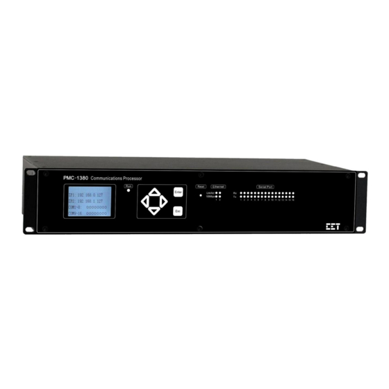
Ceiec Electric Technology Chapter 2 Installation 2.1 Appearance Figure 2-1 Front Panel Figure 2-2 Rear Panel 2.2 Mounting The PMC-1380-3 should be installed in a dry environment with no dust and kept away from heat, radiation and electrical noise source. -
Page 9: Wiring Connections
Ceiec Electric Technology 2.3 Power Supply Wiring Please consult the serial number label to ensure that the supply voltage is within the range of the PMC-1380-3’s power supply specifications. For AC supply, connect the live wire to the L/+ terminal and the neutral wire to the N/- terminal. For DC supply, connect the positive wire to the L/+ terminal and the negative wire to the N/- terminal. -
Page 10: Serial Port Wiring
Ceiec Electric Technology 4,5,7,8 Receive Data- Table 2-1 RJ45 Connector Pin Description for 10/100BaseT Applications 2.5.1 Straight through Connection A straight through RJ45 cable should be used if the PMC-1380 is connected to an Ethernet switch or hub. The following figure illustrates the definition of an 8-pin RJ45 straight through cable. The... - Page 11 Ceiec Electric Technology Figure 2-9 DB9 Female Connector 2.6.1 RS-232 (DTE) Pin Definition RS-232 Description No Connect Receive Data Transmit Data No connect Ground No connect No connect No connect No connect Table 2-2 RS-232 Pin Definition 2.6.2 RS-485 Pin Definition...
-
Page 12: Chapter 3 Operating The Pmc-1380-3
Ceiec Electric Technology Chapter 3 Operating the PMC-1380-3 3.1 Front Panel 3.1.1 LED Indicators There are several LED indicators on the PMC-1380-3’s front panel as described in the following table. LED Indicator Color Function Green Power is on and the PMC-1380-3 is running normally... -
Page 13: Typical Applications
Ceiec Electric Technology IP Address Subnet Settings Network Ethernet 1 to 2 Mask Gateway IP Address Subnet Setup Network Ethernet 1 to 2 Mask Gateway Change Main Menu Password Maintenance Set Clock Contrast Setup Model Version Version Update Info Diagnostics... - Page 14 Ceiec Electric Technology 3.2.1 Single Networking This architecture shown in Figure 3-3 below is typically used in smaller applications where there is only a single networking backbone. This networking topology features a simple structure that is easy to maintain, cost-effective and suitable for applications where redundant networking is not available or required.
- Page 15 Ceiec Electric Technology 3.2.2 Dual Networking The architecture shown in Figure 3-4 provides physical networking redundancy for applications where data availability and security are of critical importance. The dual networking topology provides a backup backbone which allows communications to be re-routed at the application level in the event that the main backbone fails.
-
Page 16: Chapter 4 Configuring The Pmc-1380-3 Via The Web Console
Ceiec Electric Technology Chapter 4 Configuring the PMC-1380-3 via the Web Console PMC-1380-3 Web Console has two programming modes: On-Line and Off-Line. The On-Line mode is used to query and configure a connected PMC-1380-3, while the Off-Line mode is used to configure a PMC-1380-3 without physically connecting to a PMC-1380-3. -
Page 17: Off-Line Web Console Login
Ceiec Electric Technology 3) Enter the IP Address of the PMC-1380-3 in the Address input box of the Internet Protocol (TCP/IP) Properties dialog box and then press <Enter>. The default IP address is 192.168.0.127 for Ethernet 1 and 192.168.1.127 for Ethernet 2. -
Page 18: Network Settings
Ceiec Electric Technology Option Description Setting If the user is running it for first time, the New Last Configuration Configuration should be used; otherwise, select Last Configuration Default: Select the model and then perform configuration New Configuration PMC-1380-3-RR-00-16- based on its default one... -
Page 19: Time Settings
Ceiec Electric Technology 3) Click <Submit> at the upper left-hand corner of the right-hand pane to store the new configuration in a local cache before leaving this page. 4) Click <Save> at the upper right-hand corner of the web page to save the new configuration to the device’s configuration file that is stored on the PC for Off-Line programming or to download the... - Page 20 Ceiec Electric Technology This option exists in both the On-Line and Off-Line programming modes. Click on Channel Settings under Channel Management on the left-hand pane and the following screen appears. Double-click on a particular channel or click on the right to modify the channel settings. The Edit dialog box is shown below.
- Page 21 Ceiec Electric Technology 3) Click <Save> at the upper right-hand corner of the web page to save the new configuration to the device’s configuration file that is stored on the PC for Off-Line programming or to download the new configuration to the PMC-1380-3 for On-Line programming.
-
Page 22: Driver Management
Ceiec Electric Technology new configuration to the PMC-1380-3 for On-Line programming. 3) Click <Quit> to leave the PMC-1380-3 Web Console. Please ensure that your changes have been saved before leaving. Advanced Settings Option Description Setting 0 to 60000 ms Polling Delay... -
Page 23: Slave Ied Management
Ceiec Electric Technology Click on Driver Management under Channel Management on the left-hand pane and the following screen appears. Option Description Setting Add Driver Add a new Driver Select All Select all drivers Remove Driver Remove the selected (checked) driver(s) - Page 24 Ceiec Electric Technology Driver Driver description Unit ID Slave IED Unit ID Enable the collection of Waveform Enable or Disable Waveform Record Records for CET devices that support Default = Disable this feature Reserved Enter extended parameters NULL = Default Data Map View Driver’s Data Map for the IED...
-
Page 25: Data Cache Management
Ceiec Electric Technology Digital Output data Description Parameter name Maximum 31 characters Unit Measurement unit Notes: 1) Click <Submit> at the upper left-hand corner of the right-hand pane to store the new configuration in a local cache before leaving this page. -
Page 26: Data Cache
Ceiec Electric Technology Option Description Setting Enable or Disable Enable Enable the Data Cache Default = Disable Description Data Cache Name Default = Data Cache X Slave Protocol Slave Protocol Default = Modbus TCP 1 to 65535 IP Port IP Port number... -
Page 27: Password Reset
Ceiec Electric Technology Option Description Setting Data Cache X Select which Cache to modify Add Parameters Add parameters to the selected Data Cache Copy parameters from the selected Data Cache to another Copy Data Cache Export Parameters Export all the parameters in selected Data Cache to Excel... -
Page 28: Backup/Restore
Ceiec Electric Technology Click on Password Reset under System Maintenance on the left-hand pane and the following screen appears. Click Reset to reset the user name and password to the factory default settings. After Reset, the User Name and Password become user and 123456, respectively. -
Page 29: System Information
Ceiec Electric Technology Option Description Setting Create a backup copy, named “cmdata.cfg”, of the Web Backup Configuration Console’s configuration on the local computer. Select a configuration file on the local computer to Browse restore to the Web Console Restore Configuration Restore the selected configuration to the Web Console Reset all settings of the Web Console’s configuration file... -
Page 30: Statistics
Ceiec Electric Technology Option Description Setting Default = Model Select the correct model for configuration PMC-1380-3-RR-00-16-2-N-F0T2-XX -XXXX-E Default = PMC-1380-3 Name Specify a name for the PMC-1380-3 (Max. 31 characters) Version Firmware Version Date Firmware’s Date and Time Device’s Serial Number... -
Page 31: Clear History
Ceiec Electric Technology 4.14 Clear History This option only exists in the On-Line Web Console. Click on Clear History under System Maintenance on the left-hand pane and the following screen appears. Click on Clear History at the upper left-hand corner of the right-hand pane to execute the Clear History operation, which would clear all Data Logs, Waveform Records and SOE Logs. - Page 32 Ceiec Electric Technology...
-
Page 33: Appendix A Technical Specifications
Ceiec Electric Technology Appendix A Technical Specifications Ethernet Ports (1, 2, 3, 4) Number Connector RJ45 Ports 1, 2 10/100BaseT Ports 3, 4 (Optional) 10/100BaseT Ports 3, 4 (Optional) 100BaseFX (ST Connector) Serial Ports Number Type RS-232 (DTE) / RS-485... -
Page 34: Appendix B Standards Compliance
Ceiec Electric Technology Standards Appendix B Compliance Safety Requirements Insulation IEC 60255-5-2000 Dielectric Test 2kV @ 1 minute Insulation Resistance >100MΩ Impulse Voltage Electromagnetic Compatibility Electrostatic Discharge IEC 61000-4-2:2008 Level IV Radiated Fields IEC 61000-4-3:2008 Level III Fast Transients IEC 61000-4-4:2004 Level IV... -
Page 35: Appendix C Ordering Guide
Ceiec Electric Technology Appendix C Ordering Guide Contact us Ceiec Electric Technology Headquarters 8/F, Westside, Building 201, Terra Industrial & Tradepark, Che Gong Miao, Shenzhen, Guangdong, P.R.China 518040 Tel: +86.755.8341.5187 Fax: +86.755.8341.0291 Email: sales@cet-global.com Web: www.cet-global.com...
Need help?
Do you have a question about the PMC-1380-3 Series and is the answer not in the manual?
Questions and answers