
Summary of Contents for FireFlex Systems Inc. DUAL
- Page 1 Integrated Fire Protection System ® DUAL Owner's Operation and Maintenance Manual Double Interlocked Preaction Novec 1230 Self-contained system FM-0860-0-17G...
- Page 2 ® DUAL is a registered trademark of F Systems Inc. Systems Inc. reserves the right to make changes to this manual and the data sheets herewith at any time, without prior notification.
-
Page 3: Table Of Contents
® DUAL Page iii Integrated Fire Protection System & M WNER PERATION AINTENANCE ANUAL Table of Contents 1. GENERAL ................................. 1 1.1 APPLICABLE STANDARDS .............................. 1 1.2 LISTINGS & APPROVALS ..............................1 1.3 ENVIRONMENT ................................1 1.5 FEATURES ..................................2 1.6 CONFIGURATION ................................ - Page 4 ® DUAL Page iv Integrated Fire Protection System & M WNER PERATION AINTENANCE ANUAL 6. CONTROLS ................................23 6.1 PRODUCT DESCRIPTION .............................. 23 6.2 NFS-320 CONTROL PANEL ............................23 7. WIRING DIAGRAMS ............................. 25 8. CABINET................................. 26 9. LIMITED WARRANTY ............................28...
-
Page 5: General
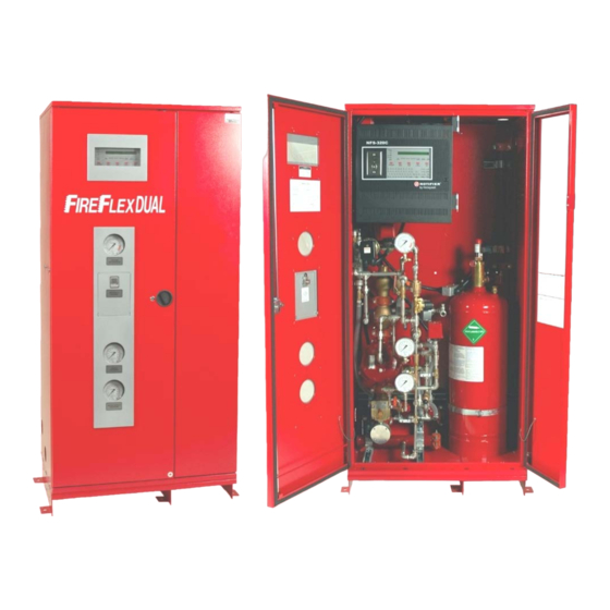
14 gauge steel with a rustproof fire red paint finish, polyester powder coated and oven baked ® DUAL unit shall be installed in a dry and clean on a phosphate base. Each cabinet is provided with two location. Verify that all equipment are properly heated and frontal locked doors, reducing space requirements for ease protected to prevent freezing and physical damage. -
Page 6: Features
1.6 CONFIGURATION ® Configuration for DUAL: ® DUAL main features are: • Engineered NOVEC 1230 single cylinder with electric • Trouble-free design for safe and easy application release • Available in 3 cabinet sizes • Double interlocked preaction with electric / pneumatic •... -
Page 7: Clean Extinguishing Agent
2. CLEAN EXTINGUISHING AGENT 2.1 AGENT 2.4 SAFETY CONSIDERATIONS ® The clean extinguishing agent used in DUAL total 2.4.1 TOXICITY flooding system is NOVEC 1230. The table 2.1 identifies the toxicological data on NOVEC 1230 and compares this with HALON 1301. -
Page 8: Preaction System
Water will flow from any opened sprinklers in the 3.2 CONFIGURATION system piping. ® DUAL preaction system is built around the Viking trim using deluge valve model F-1. Note: If the detection system does not operate The valve is rated up to a maximum of 250 psi (17.2 bar) properly, the deluge valve (A1) will not open. -
Page 9: Installation, Operation & Maintenance Instructions
See figures 4.5 & 4.6 at the end of the current section. ® IMPORTANT ! The DUAL unit ® DUAL cabinet shall be firmly anchored designed to be installed in area subject to freezing to the floor. conditions. Refer to section 1.3 ENVIRONMENT for 2. Open door to mechanical section. -
Page 10: Placing System In Service
® DUAL Page 6 of 28 Integrated Fire Protection System & M WNER PERATION AINTENANCE ANUAL 4.3 PLACING SYSTEM IN SERVICE Table 4.1 - Cylinder pressure versus temperature 1. Check all detectors. Cylinder pressure Temperature 2. Check all manual pull stations. -
Page 11: Sequence Of Operation
® DUAL Page 7 of 28 Integrated Fire Protection System & M WNER PERATION AINTENANCE ANUAL 4.4 SEQUENCE OF OPERATION e) “PRE-DISCHARGE” and "DISCHARGE" lamps illuminate steady. 4.4.1 Automatic release f) Preaction solenoid valve (F1) activates. 1. Actuation of a detector from one detection zone: Note: Preaction piping network will not yet be filled with a) “ZONE 1”... -
Page 12: Emergency Instructions
® DUAL Page 8 of 28 Integrated Fire Protection System & M WNER PERATION AINTENANCE ANUAL 4.5 EMERGENCY INSTRUCTIONS To take system out of service: WARNING ! Placing a system out of service may eliminate the fire protection capabilities of the system. -
Page 13: Placing The System Back In Service After Operation
® DUAL Page 9 of 28 Integrated Fire Protection System & M WNER PERATION AINTENANCE ANUAL 4.6 PLACING THE SYSTEM BACK IN SERVICE AFTER 4.7 ELECTRIC ACTUATOR OPERATION When the electric actuator (C) gets energized, it stays in See figures 4.5 & 4.6 at the end of the current section. -
Page 14: Inspections & Tests
® DUAL Page 10 of 28 Integrated Fire Protection System & M WNER PERATION AINTENANCE ANUAL 4.8 INSPECTIONS & TESTS When testing is complete, return the system to service: NOTICE: THE OWNER RESPONSIBLE 1. Verify that the pressure indicated on pressure... -
Page 15: Maintenance
® DUAL Page 11 of 28 Integrated Fire Protection System & M WNER PERATION AINTENANCE ANUAL 4.8.3 Main drain test 6. Check to insure that the nozzles are positioned correctly. A main drain test shall be conducted to determine whether there has been a change in the condition of the water supply 7. - Page 16 Page 12 of 28 Integrated Fire Protection System & M WNER PERATION AINTENANCE ANUAL ® Figure 4.4 - DUAL (shown without doors) Clean agent outlet Air compressor Isolation switch Junction box TBA, TBB & TBC Releasing circuit disable switch Air compressor...
- Page 17 Integrated Fire Protection System & M WNER PERATION AINTENANCE ANUAL ® Figure 4.5 - DUAL - Double interlocked preaction trim From Air Supply System Trim From Air Supply System Trim Field connection to sprinklers piping From Air Supply System Trim...
- Page 18 Page 14 of 28 Integrated Fire Protection System & M WNER PERATION AINTENANCE ANUAL ® Figure 4.6 - DUAL - NOVEC 1230 trim Field connection to NOVEC 1230 piping DUAL base (shown without enclosure) FM-076Z-0-16B-2 Components: A Cylinder E Liquid level indicator...
-
Page 19: Optional Shut-Off Valve And Sight Glass
The shut-off valve & sight glass option is intended to be used ® When required by the user, DUAL unit can be for applications where testing of the system operation without provided in a semi-flanged configuration. filling the sprinkler piping network is desirable and where it is... -
Page 20: Preaction Air Supplies
220Vac, 50/60Hz. ® DUAL cabinet (see figure 6.2) and is factory wired, allowing powering off the air compressor while some ♦ Air supply Style "B" maintenance work on the unit is done, without disturbing the See figure 5.4. -
Page 21: Operation
® DUAL Page 17 of 28 Integrated Fire Protection System & M WNER PERATION AINTENANCE ANUAL 5.3 OPERATION Figure 5.2 - Front view of the air compressor cut-off pressure switch ♦ Air supply Style "A" See figure 5.3. Turn clockwise to increase... -
Page 22: Maintenance And Inspection
® DUAL Page 18 of 28 Integrated Fire Protection System & M WNER PERATION AINTENANCE ANUAL ♦ Air supply Style "B" 5.4 MAINTENANCE AND INSPECTION See figure 5.4. ♦ Air supply style "A" The Viking model D-2 air pressure maintenance device See figure 5.3. - Page 23 ® DUAL Page 19 of 28 Integrated Fire Protection System & M WNER PERATION AINTENANCE ANUAL Table 5.3 - Pressure adjustments Air supply Compressor Compressor Low air Low air System type style regulator Start Stop supervisory alarm 30 psi 35 psi...
- Page 24 ® DUAL Page 20 of 28 Integrated Fire Protection System & M WNER PERATION AINTENANCE ANUAL Figure 5.3 – Air supply Style "A" (Cabinet mounted air compressor) Pressure relief valve This section replaced by Dehydrator option (when used) (plugged with...
- Page 25 ® DUAL Page 21 of 28 Integrated Fire Protection System & M WNER PERATION AINTENANCE ANUAL Figure 5.4 – Air supply Style "B" (APMD without air compressor) This section replaced by Dehydrator option (when used) (plugged with SureFire trim) Contractor external Air...
-
Page 26: Dehydrator Option
® DUAL Page 22 of 28 Integrated Fire Protection System & M WNER PERATION AINTENANCE ANUAL 5.5 DEHYDRATOR OPTION 3. The maximum air flow rating is 15 ft /minute (0.425 m /minute) at 100 psi (6.89 bar) for each unit. -
Page 27: Controls
Although the NFS-320 is primarily designed to be used with addressable devices, all devices to ® be connected to the DUAL unit must be conventional type. In fire conditions when an initiating device circuit (or predetermined combination of circuits) is energized, the panel activates the release and signaling circuits according to the factory set programming. - Page 28 ® DUAL Page 24 of 28 Integrated Fire Protection System & M WNER PERATION AINTENANCE ANUAL Figure 6.2 - Control equipment layout Disengage hook for rotation of control panel Air compressor isolation switch (E15) (via junction box) Junction box TBA & TBB...
-
Page 29: Wiring Diagrams
® DUAL Page 25 of 28 Integrated Fire Protection System & M WNER PERATION AINTENANCE ANUAL 7. WIRING DIAGRAMS Figure 7.1 - Field wiring diagrams AC POWER SOURCE INPUTS CLASS A DETECTION CLASS B DETECTION XP6-MA XP6-MA WITH A/B UNSELECTED... -
Page 30: Cabinet
8. CABINET ® Figure 8.1 - Drilling details DUAL cabinet is made of sturdy 14 gauge steel. Refer to table 8.1 and figure 2 for dimensions. All surfaces are rust proof coated, inside and outside, with fire red, oven baked polyester powder on phosphate base. - Page 31 ® DUAL Page 27 of 28 Integrated Fire Protection System & M WNER PERATION AINTENANCE ANUAL Figure 2 - Cabinet dimensions R Ø 12'' 12'' 22'' FM-061H-1-49B-7 Ø3/4" 2"Ø H Ø FM-061H-1-49B-1 FM-061H-1-49B-6 Table 8.1 - Cabinet dimensions Table 8.3 - NOVEC 1230 piping installation Size 77⅛"...
-
Page 32: Limited Warranty
® DUAL Page 28 of 28 Integrated Fire Protection System & M WNER PERATION AINTENANCE ANUAL 9. Limited Warranty FireFlex Defective part(s) must be returned to the address listed Systems Inc. (known herein "the below within (30) days of receiving replacement parts(s). If Manufacturer") warrants to its customer that its products...
Need help?
Do you have a question about the DUAL and is the answer not in the manual?
Questions and answers