
Subscribe to Our Youtube Channel
Related Manuals for Dolphin 9013-25


Summary of Contents for Dolphin 9013-25
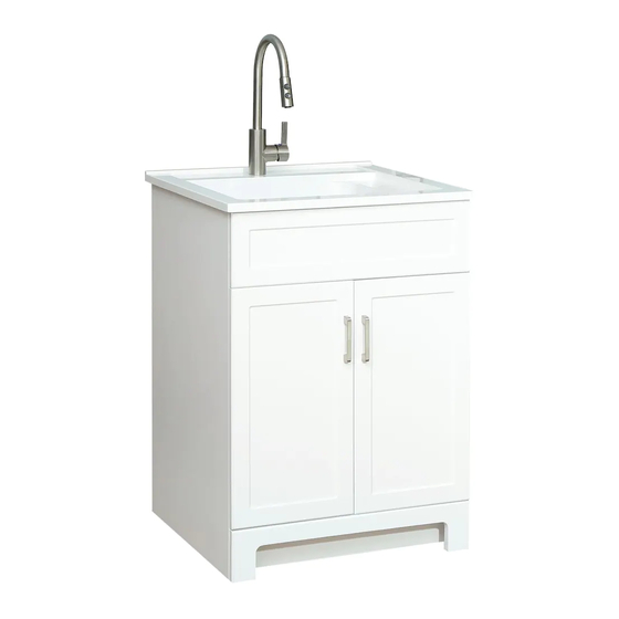
- Page 1 Installation Instructions Instructions d'installation 9013-25 25 in. LAUNDRY CABINET WITH COMPOSITE LAUNDRY TOP THANK YOU...
-
Page 2: Table Of Contents
Table of Contents Table of Contents ............2 Laundry Cabinet Dimensions ..........3 Safety Information ............2 Tools Required .................3 Warranty ................. 2 Hardware Included ..............3 Care and Cleaning ............2 Package Contents ..............4 Pre-Assembly ..............3 ................Assembly 5-10 Planning Assembly ..............3 Safety Information Please read and understand all instructions before assembly and... -
Page 3: Pre-Assembly
Pre-Assembly PLANNING ASSEMBLY Check the laundry cabinet for damage before installation. If any part of the laundry cabinet is missing or damaged, contact the Customer Service Team at 1- 855-HD-GLACIER. Ensure that the laundry cabinet location is accessible to water supply and drain lines. It is suggested that you rough-in the water lines and drain before installing the laundry cabinet. -
Page 4: Package Contents
Pre-Assembly (continued) PACKAGE CONTENTS Part Part Description Quantity Part Part Description Quantity Sink top Faucet Laundry cabinet Sprayer Top drain pipe Rubber gasket Metal gasket Gasket Bottom drain pipe Trap seal primer Curved drain pipe Quick connector Weight... -
Page 5: Assembly
Assembly Installing the strainer Installing the strainer (continued) □ Components of the strainer. □ Add a small bead of silicone to the top of drain hole. □ □ Installing the strainer (continued) Completing the strainer installation □ Strainer installation complete. □... - Page 6 Assembly (continued) Installing the P-trap □ Assemble the P-trap together by attaching the gasket (E) on the bottom of the top drain pipe (C), attaching the top drain pipe (C) and bottom drain pipe (F) to the curved drain pipe (G), and securing the connections by twisting the nuts (D) onto the threaded ends of curved drain pipe (G).
- Page 7 Assembly (continued) Installing the vanity □ Decide exactly where you wish to install your vanity and gently put it down on the floor □ □ Installing the handle □ Remove all the handles (BB) from the back of door...
- Page 8 Assembly (continued) Installing the handle □ Install the handles (BB) on the front of the doors. □ □ Installing the sink □ Add a small bead of silicone to the top perimeter of the cabinet (B) where contact will be made with the sink. □...
- Page 9 Assembly (continued) Preparing to install the faucet Installing the faucet □ Make sure the installation location for the faucet will meet □ Insert the faucet body (H) into the center mounting hole on the sink. these size requirements: unit:mm □ □...
- Page 10 Assembly (continued) Install the trap seal primer Connecting the pull-out hose □ □ Screw the primer (M) on the end of the outlet pipe. Unscrew the quick connector (N) from the end of the outlet pipe. The connection will make a click sound. This indicates a □...
- Page 12 Installation Instructions Instructions d'installation 9013-25 ARMOIRE DE BUANDERIE DE 64 CM AVEC DESSUS EN LAVAGE COMPOSITE MERCI...
-
Page 13: Garantie
Table des matières Dimensions de l'armoire de buanderie ........3 Table des matières ............2 Outils requis ................3 Consignes de sécurité ..........2 Garantie ................2 Visserie fournie ................ 3 Entretien et nettoyage ..........2 Contenu du paquet ..............4 Avant l'assemblage ............ -
Page 14: Avant L'assemblage
Avant l'assemblage PLANIFICATION DE L'ASSEMBLAGE Vérifiez l'état de l'armoire de buanderie avant installation. Si une quelconque pièce de l'armoire de buanderie manque ou est endommagée, contactez le service clientèle au 1-855-HD-GLACIER. Assurez-vous que l'emplacement de l'armoire de buanderie est accessible aux conduites d'arrivée d'eau et de vidange. -
Page 15: Contenu Du Paquet
Avant l'assemblage (suite) CONTENU DU PAQUET Pièce Description Quantité Pièce Description Quantité Robinet Dessus du lavabo Armoire de buanderie Douchette Joint en caoutchouc Tuyau de vidange supérieur Joint métallique Écrou Écrou Joint Amorceur de siphon Tuyau de vidange inférieur Connecteur rapide Poids Tuyau de vidange incurvé... -
Page 16: Assemblage
Assemblage Installation de la crépine Installation de la crépine (suite) □ □ Ajouter un cordon de silicone mince en haut du Composants de la crépine. trou de vidange. □ □ Fin d'installation de la crépine Installation de la crépine (suite) □... - Page 17 Assemblage (suite) Installation du siphon P □ Assembler le siphon P en attachant le joint (E) en bas du tuyau de vidange supérieur (C), en attachant le tuyau de vidange supérieur (C) et le tuyau de vidange inférieur (F) au tuyau de vidange incurvé (G), et en établissant les raccordements en tournant les écrous (D) sur les extrémités filetées du tuyau de vidange incurvé...
- Page 18 Assemblage (suite) Installation du meuble-lavabo □ Déterminez l'emplacement exact où vous souhaitez installer le meuble-lavabo et déposez le doucement sur le sol. □ □ Installation du poignées □ Retirez toutes les poignées (BB) fixées à l'intérieur des porte.
- Page 19 Assemblage (suite) Installation du poignées □ Installez les poignées sur le devant des porte. □ □ Installation du lavabo □ Appliquer un cordon de silicone mince au périmètre supérieur de l'armoire (B) là où se fera le contact avec le lavabo. □...
- Page 20 Assemblage (suite) Installation du robinet Préparation à l'installation du robinet □ □ S'assurer que le lieu d'installation pour le robinet sera Insérer le corps du robinet (H) dans le trou central du lavabo. conforme à ces dimensions exigées : unité : mm □...
- Page 21 Assemblage (suite) Installation de l'amorceur Raccordement du tuyau flexible de siphon rétractable □ □ Dévisser le connecteur rapide (N) de l'extrémité du tuyau Visser l'amorceur de siphon (M) à l'extrémité du tuyau de sortie. de sortie. Le raccordement est signalé par un déclic. Ceci indique une □...
Need help?
Do you have a question about the 9013-25 and is the answer not in the manual?
Questions and answers