Advertisement
Quick Links
Complementary Material to ProboStat™ Manual
As we are always learning from feedback from our customers and users, and for giving better understanding of
the ProboStat™ sample holder, we present this note as a complementary material to the ProboStat™ Manual.
The main goal of this document is explanation of the ProboStat™ system design which is not covered in the
Manual.
1.
ProboStat™ Gas Supply System
1.1.
Recommended reading
First, we recommend familiarizing youself with:
a) ProboStat™ Manual:
Part 2 "Safety first", pp. 2-1 – 2-2,
Part 4.2.4 "Gas connects", pp. 4-5 – 4-7,
Part 4.4 "Support tubes", pp. 4-12 – 4.13,
Part 4.5 "Gas supply tubes", pp. 4-13 – 4-14,
Part 6.3 "Pressures, vacuum, leakage rates, atmosphere purity", pp. 6-1 – 6-2,
Part 7.3 "Gas tightness", pp. 7-4 – 7-5,
Part 9.3 "Over-atmospheric pressure", pp. 9-3 – 9-4,
Part 9.4 "Wet gases with dew-point above room temperature", p. 9-4,
Part 12.1.4 "Inner gas tubes", pp. 12-4 – 12-6.
b) NorECs web page www.norecs.com :
FAQ – atmosphere control
FAQ – sealing
1.2.
Single and dual atmosphere modes
The ProboStat™ is a sample holder designed to perform experiments in single or dual atmosphere modes
at near-atmospheric total pressure, and can be fed with virtually any gas.
Single atmosphere mode
1.2.1.
The term "single atmosphere mode" means that one gas is fed in both inner and outer ProboStat™ gas
compartments. The single atmosphere mode is used for:
ProboStat™ Starting Guide
2
Advertisement

Related Manuals for Norecs ProboStat

Summary of Contents for Norecs ProboStat
- Page 1 As we are always learning from feedback from our customers and users, and for giving better understanding of the ProboStat™ sample holder, we present this note as a complementary material to the ProboStat™ Manual. The main goal of this document is explanation of the ProboStat™ system design which is not covered in the Manual.
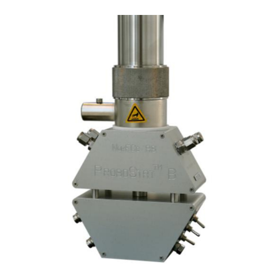
- Page 2 (yellow colour). The inner and outer ProboStat gas compartments are marked “INNER” and “OUTER”. Each compartment has gas inlet and outlet quick-connects appropriately marked “IN” and “OUT”, resulting in “INNER IN”, “INNER OUT”, “OUTER IN”, and “OUTER OUT”.
- Page 3 Complementary Material to ProboStat™ Manual Fig. 1: SS and brass base units. Fig. 2: IN and OUT quick- Fig. 3: SS bulkheads mounted connects for INNER on top part of splitted and OUTER gas hexagon. compartments. 1.3.2. Gas stems As standard, the quick-connects are matched by four quick-connect stems for connecting to 1/8’’ tubing.
- Page 4 The gas stub for the outer gas compartment is made of SS and assembled by two Viton sealing O-ring. The SS gas stub is set into the lower part of base unit body. Fig. 6: ProboStat™ PEEK and SS gas stubs Fig. 7: ProboStat™ base unit with gas stubs...
- Page 5 1.4. Base unit sealing O-rings The ProboStat base units can be supplied with Viton or Isolast sealing O-rings depending on the base unit operating temperature. The standard base units are equipped with Viton O-rings, the high-temperature one – with Isolast version.
- Page 6 1.5. Gas supply tubes The ProboStat™ is supplied with various gas supply tubes. These are to be used inside the cell to supply gases directly to the sample area. Table 4: Standard gas supply tubes delivered with the ProboStat™. *...
- Page 7 Table 5. Assembling ProboStat™ gas compartments. Step 1: Step 2: Place the ProboStat base unit on the bench, Mount the inner gas supply tube onto the PEEK gas preferably fix it in a lab stand using a bar for base stub.
- Page 8 Complementary Material to ProboStat™ Manual Step 3: Mount the sample support tube tight. Step 4: Place an Au sealing ring on top of the sample support tube. * *This step is relevant for the gas compartments separation. If you plan to measure using the single...
- Page 9 Complementary Material to ProboStat™ Manual Step 5: Place a sample on top of the gold ring (or Step 6: Mount outer bent silica (a) or straight directly on the sample support tube for the single alumina (b) gas tube onto the SS gas stub.
- Page 10 Complementary Material to ProboStat™ Manual Step 6: Mount outer bent silica (a) or straight Step 7: Mount enclosing quartz or alumina tube alumina (b) gas tube onto the SS gas stub. and O-ring.* *For simplicity the spring load assembly is not explained or drawn here.
- Page 11 Complementary Material to ProboStat™ Manual Step 8: Fasten the base unit flange.
-
Page 12: Recommended Reading
Complementary Material to ProboStat™ Manual ProboStat™ electrical system In this part we describe ProboStat™ electrode contact assemblies, base unit electrical wiring, and coaxial cables. 2.1. Recommended reading We recommend familiarizing youself with: a) ProboStat™ Manual: Part 4.2.6 “Electrical feedthroughs”, pp. 4-7 – 4-8, ... - Page 13 Complementary Material to ProboStat™ Manual Tabel 7. ProboStat™ electrode contacts. H2N# INH2N12...
- Page 14 Complementary Material to ProboStat™ Manual...
- Page 15 Complementary Material to ProboStat™ Manual H1TN10 H1BN10 vdP2...
- Page 16 Complementary Material to ProboStat™ Manual 2.2.2. High-voltage electrode contacts High-voltage (HV) electrode contacts are suitable for connection to special feedthroughs on the HV base unit. The HV base units are made upon request and usually not a matter for the detailed description.
-
Page 17: Base Unit Wiring
The coding and functions are listed in detail in the table below. We strongly recommend users to print the Wiring Overview (page 14-2 or 14-3 in the ProboStat™ manual) and hang it on a wall next to the ProboStat™ assembling point. - Page 18 The base unit shown here is for A- 3 and higher. For A-2/A-1/B the outer In and Out gas paths (on the outer circle) are swapped. Standard electrical wiring of ProboStat versions A-2 and later, using S-type thermocouples. Function 1 P Green NiCr...
- Page 19 Complementary Material to ProboStat™ Manual Fig. 10. Phoenix-type multi-connector wiring overview. 2.3.3. Overview of base unit electrical feedthroughs By electrical feedthrough we mean an assembly where the electrical lead goes through the base unit chassis from the electrode contacts to BNC contacts mounted on the base unit hexagon. The electrical feedthrough consists of male mini-contact, sitting in PEEK insulator, and soldered to compensation wire.
- Page 20 2.3.5. Signal and shield feedthroughs The ProboStat™ base unit has 10 electrical feedthroughs, 6 of them lead current or voltage signal, 4 - shield. The signal feedthroughs are soldered to the center of the BNC contacts, shields – to the plates.
- Page 21 2.4. Coaxial cables The ProboStat™ is supplied with four identical shielded coaxial cables. The cables have color marks at the both ends for convenient use. These color marks have nothing to do with any codes or denotation on the ProboStat™ or measurement instruments.
- Page 22 3.2. Thermocouple assemblies Thermocouple assemblies (hereafter called thermocouples) are assigned to control/read temperature in the high-temperature zone of the ProboStat™ cell. 3.2.1. Description and denotation The thermocouples come in variety of types listed in the Tables 9 - 10. Table 9. Thermocouples denotation...
- Page 23 Complementary Material to ProboStat™ Manual Table 10. ProboStat™ S-type thermocouple assemblies. TCC/D TCC/B TCT/B TCB/B...
- Page 24 3.4. ProboStat™ thermocouple wiring Three thermocouples can be connected to the ProboStat™ base unit, one - in the inner gas compartments, and two – from the outer one, see the Wiring overview (p. 19). The thermocouples have denotations starting with TC.
- Page 25 Complementary Material to ProboStat™ Manual The thermocouple feedthroughs are marked with color code dots on the base unit: black and red or green and white. The thermocouple feedthroughs lead voltage from the thermocouple tip in the high-temperature zone via base unit chassis to thermocouple socket mounted on the base unit hexagon. The thermocouple sockets mounted on the S-type base unit have orange color, mounted on the K-type base unit –...
- Page 26 3.6. Control and read thermocouples The ProboStat™ thermocouple can function as a control thermocouple for the furnace. In this mode the temperature in the system is controlled by the ProboStat™ thermocouple. In the reading mode the temperature in the system is controlled by the furnace thermocouple. The furnace and the ProboStat™...
- Page 27 Complementary Material to ProboStat™ Manual 4.2. Triangular top plate spring load assembly The standard triangular top plate spring load assembly is used to press samples against the sample support tube and thereby also to hold electrode contacts in contact with the electrodes. This spring load assembly is used in all measurement setups except van der Pauw.
- Page 28 Two bars van der Pauw spring load assembly 4.4.2. In order to use this assembly, you need four electrode contacts. Please see the ProboStat™ manual. Fig. 25. Top part of van der Pauw setup. The spring load assembly is marked by light-blue color.
- Page 29 Part 4.2.3. “Connector box and cooling water ring; change angle of the fixation bar”, pp. 4-4 – 4-5. Cooling water hose can be connected to the ProboStat™ base unit via two stubs on a water cooling cylinder. The water flows between the water cooling cylinder and the central base unit block and is sealed with two permanently compressed water cooling O-rings inside.
- Page 30 Complementary Material to ProboStat™ Manual Fig.27. Cooling water hose stubs on Fig. 28. Water cooling O- Fig.29. Cooling water connected. water cooling cylinder. rings. ProboStat™ Earth On the base unit hexagon you can you can also find Earth point screw that is used for external Earth connection.
- Page 31 Assembling 2-point impedance spectroscopy and conductivity measurements on disk sample 7.1.1. List of accessories In order to find out all parts you need for this method, you should refer to Figure 8-1 in the ProboStat™ manual. Fig. 31. Figure 8-1 in the ProboStat™ manual.
- Page 32 Complementary Material to ProboStat™ Manual Accordingly, the next accessories should be used: 1. Inner gas supply tube (optional). 2. Inner thermocouple TCI/D (optional). 3. Sample support tube assembly for disk sample. 4. Sample support plate. 5. Two electrode “hand” contact assembly, outer, 2-wire (H2N#).