
Summary of Contents for Larzep HAB1101
- Page 1 INSTRUCTIONS & MAINTENANCE SHEET PORTABLE BATTERY HYDRAULIC POWERPACK HAB1101 LARZEP, S.A. Avenida Urtiaga, 6 48269 MALLABIA, SPAIN Tel. +34 943 171200 Fax. +34 943 174166 e‐mail: sales@larzep.com www.larzep.com V12.2012 ...
-
Page 2: Technical Characteristics
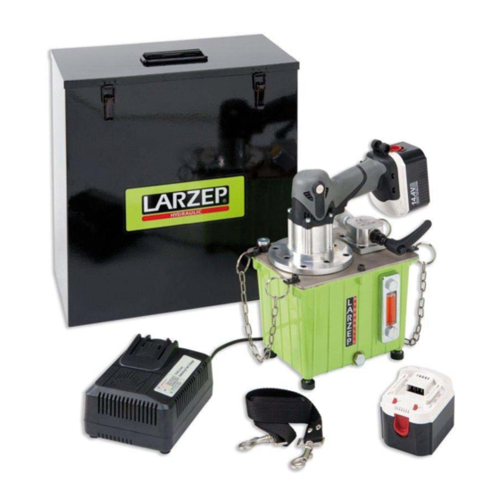
RECEPTION Visually inspect all the components to check for damage during transport. Should you observe any deterioration at all, please inform the transport company or tool distributor immediately. DESCRIPTION The HAB1101 mains‐powered hydraulic unit is compact and lightweight and is therefore suitable for use as a portable hydraulic power distribution centre. It has been designed for use with any tool requiring an operating pressure of up to 700 bar (10.000 psi). The unit is supplied with a quick connector, and a metal carrying and storage box. ... -
Page 3: Battery Removal And Installation
3. START UP Before using the Mains‐Operated Hydraulic Unit, ensure that you have read both the general safety instructions and the operating instructions. 1. Place the Release Valve lever in the "pressure" position. 2. Press the push button. PUSH BUTTON 3. Perform the work specific to the head or cylinder being used. Maximum working pressure 700 bar. 4. To depressurise, place the Release valve lever in the "release" position and the pressure is released automatically. 5. -
Page 4: Battery Installation
BATTERY INSTALLATION Insert the battery ensuring that the poles are correct (see previous figures). BATTERY CHARGING Before using the tools, charge the battery as follows: ‐ Plug the charger cable into an AC socket. Once the charger plug has been connected to the mains, the red pilot light will light continuously. ‐ Insert the battery in the charger Firmly insert the battery, in the direction indicated in the following . figure, until it comes into contact with the charger compartment bottom. CAUTION: If the battery is inserted the wrong way round, apart from not charging this could also damage the charger, such as the deformation of the charging terminal. ‐ Charging. When the battery is inserted into the charger, it will start to charge and the red pilot light will be on continuously. Once the battery is completely charged, the green pilot light will flash (at one second intervals). See the following table. ... -
Page 5: Care And Maintenance
How to make the batteries perform longer ‐ Recharge the batteries before they become completely exhausted. When you feel that the power of the tool becomes weaker, stop using the tool and recharge its battery. If you continue to use the tool and exhaust the electric current, the battery may be damaged and its life will become shorter. ‐ Avoid recharging at high temperatures. A rechargeable battery will be hot immediately after use. If such a battery is recharged immediately after use, its internal chemical substance will deteriorate, and the battery life will be shortened. Leave the battery and recharge it after it has cooled for a while. CAUTION ... - Page 6 ‐ Disassembly: Loosen the three screws on the unit handle cover and remove the handle cover. Remove the stopper screw in order to remove the holder plate which keeps the carbon brush holder in place. Lift out the brush holder together with the carbon brushes. Take great care not to forcibly pull the lead wires within the brush holders. Pull the brush connection terminal and remove the contact brush from the brush holder. ‐ Assembly: Place the new carbon brush in the brush holder and connect the terminal to the carbon brush. Return the brush holder and other parts to their original positions. Press the holder plate into position, securing it with the stopper screw. Place the lead wire in the specified position. Take particular care not to let the lead wire contact the armature or rotating parts of the motor. Replace the handle cover, taking care to ensure that it does not pinch the lead wire and secure it firmly with the three screws. ‐ CAUTION Ensure that the lead wire is pinched by the handle cover or come into contact with the armature or rotating ...
-
Page 7: Fault Diagnostics
WARNINGS The punches must be threaded on the stud along all its length in order to avoid the breaking of the screw or the thread. The working position of the tool, for its correct functioning should be the natural, with the handle down. 6. FAULT DIAGNOSTICS Before performing any work on the tool, ensure that it is disconnected from the mains. ATTENTION! If any maintenance that is not detailed below is required, please consult the nearest Service Centre. PROBLEM POSSIBLE CAUSE SOLUTION The tool does not advance, Oil level is low. Add oil following the instructions given above. advances slowly or intermittently. Release valve open. Close the Release valve. Loose quick connections. Check connections. Too load. Do not try to operate above the rated load. Air in the system. Bleed the circuit, keeping the pump higher than the tool and operating it several times without increasing the pressure. ... - Page 8 ...
Need help?
Do you have a question about the HAB1101 and is the answer not in the manual?
Questions and answers