Table of Contents
Advertisement
Advertisement
Table of Contents

Summary of Contents for TrafFix Scorpion II METRO TL-2 PLUS
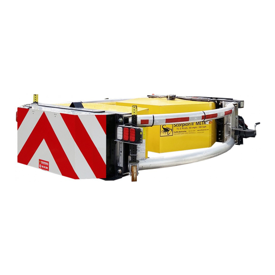
- Page 1 Scorpion II® METRO Truck Mounted Attenuator Assembly Manual and Mounting Instruction Guide (For Model: Scorpion II®METRO 10000 Series TMA) This Manual is Available at www.traffixdevices.com 160 Avenida La Pata San Clemente, CA 92673 P/N 13089 Rev A1 Dated 5/13/2020 1...
- Page 2 This Page is Intentionally Left Blank P/N 13089 Rev A1 Dated 5/13/2020 i...
- Page 3 TrafFix Devices, Inc. Certified Attenuator Installer for assistance in mounting the system is recommended. Contact TrafFix Devices, Inc. to obtain a list of Certified Installers in the area. Please read this manual in its entirety before assembling, installing, or operating the Scorpion II Metro TMA.
-
Page 4: Table Of Contents
Fast-Trak SwiftConnect™ Configuration 1……………………………………………………..35-36 Fast-Trak SwiftConnect™ Configuration 2……………………………………………………..Fast-Trak SwiftConnect™ Configuration 3……………………………………………………..38-39 Section 4 Limited TMA Warranty………...…………………………………………………….……………………..Metro TMA High Pivot…………………………..…………………………………………………………..41-44 Metro TMA Low Pivot…………………………..…………………………………………………………..45-48 TrafFix Devices, Inc. Contact Information…………………………………………………………..P/N 13089 Rev A1 Dated 5/13/2020 iii... -
Page 5: Limitations And Warnings
Limitation and Warnings TrafFix Devices Inc. (TDI), in compliance with the Manual for Assessing Safety Hardware (MASH) recommended procedures for the Safety Performance of Highway Features. TDI contracts with ISO accredited testing facilities to conduct crash tests, evaluation of tests, and submittal of results to the Federal Highway Administration for Eligibility for Federal-Aid Reimbursement. -
Page 6: Operating Instructions
Operating Instructions Proper Operation includes knowledge of TMA use in Work Zones, both Moving and Stationary, including the proper spacing, to allow for “roll-ahead”. Before use, the Operator should have prior knowledge/ discussion of the Work Zone in which the TMA will be deployed and that the TMA model used has been tested and passed to Test Level 2 PLUS, 50 mph/80 kph. - Page 7 To Raise (“Store”) the Unit for Transport 1. Ensure that both the truck bed and area above the rear of the host vehicle is clear. 2. Locate the desired controller, either the in-cab controller (if installed) or the rear plug-in. If using the rear plug-in, and it is not already plugged in, plug it into the socket on the TMA near the rear passenger side of the truck.
-
Page 8: Safety Instructions & Precautions
SAFETY INSTRUCTIONS & PRECAUTIONS A. Before attempting to install or operate the Scorpion II Metro TMA this manual should be read and understood. Those areas with warnings or cautions should be carefully followed. B. Before raising or lowering the TMA the operator should check that the area around the TMA is clear and that personnel are not in or near the area. -
Page 9: Notes
Notes: P/N 13089 Rev A1 Dated 5/13/2020 5... -
Page 10: Tma Metro Parts List- Major Components
P/N 13089 Rev A1 Dated 5/13/2020 6... - Page 11 Scorpion II Metro TMA Parts List - Major Components Item # Part # Item Description QTY/TMA Cartridge Tube Assy, LH, Includes: C-Tape, Warning Labels, Side Marker Bracket 10100L-Metro-HPP-KIT Installed Cartridge Tube Assy, RH, Includes: C-Tape, Warning Labels, Side Marker Bracket 10100R-Metro-HPP-KIT Installed 11400E...
-
Page 12: Assembly Of Scorpion Ii Metro Tma
Assembly of Scorpion II Metro TMA P/N 13089 Rev A1 Dated 5/13/2020 8... -
Page 13: Recommended* Assembly Tools
If there is anything missing or not complete, contact a TrafFix Devices representative as soon as possible. 3. WARNING: TOP HEAVY– Indicates to move pallets with extreme caution. The use of a forklift is preferred when handling pallets. -
Page 14: Pre-Assembly Checklist/Scorpion Ii Metro Registration
Initial Inspection: Compare the Packing List with the original order to ensure all items have been delivered. Should any damage be found, or any items missing, contact the freight company as well as a TrafFix Devices representative as soon as possible. -
Page 15: Remove Packaging/Tail Light & Side Marker Light Inspection
Removing Packaging for Inspection 2. Observe the warning signs before unwrapping. Module A • Remove plastic wrap and cardboard with utility knife. *Be careful not to cut any wires or parts. P/N 13089 Rev A1 Dated 5/13/2020 11... - Page 16 Unwrap and Inspect: Tail Lighting and Side Marker Lights 3. Remove all cardboard from lights and inspect for damage. Side Marker: Tail Lighting: P/N 13089 Rev A1 Dated 5/13/2020 12...
-
Page 17: Metro Tma Assembly Overview
Metro TMA Assembly Overview 1. Cut and remove Steel bands and cardboard from the TMA. 2. Remove Module A from the pallet and open the box. 3. Remove Module C from the TMA. 4. Open parts and accessory box, confirm contents. 5. - Page 18 Metro TMA Assembly Overview 6. Lift the TMA off the pallet using a forklift. 7. Remove mounting brackets from the pallet. 8. Reposition the TMA on the edge of the pallet. 9. Lower drop jacks so that the yellow paint is not showing. 10.
-
Page 19: Metro Tma Assembly
Metro TMA Assembly 1. Cut the Steel bands that are holding the components to the TMA. One person should be holding the components in place, while another person cuts the bands. WARNING: Watch for falling components when cutting the Steel Bands. Remove the components and the cardboard from the TMA. - Page 20 Metro TMA Assembly 1. Cut and remove the steel bands that hold the TMA to the pallet. Steel Bands 2. To prevent paint from getting damaged, place a piece of cardboard on the blades of the forklift. Use the forklift to lift the TMA diaphragm off the pallet.
- Page 21 Metro TMA Assembly 4. Position the TMA on the edge of the pallet then slowly start lowering the TMA. 5. Once the drop jacks can safely be reached, do not lower the TMA any further. Extend the drop jacks so that the yellow painted edge is aligned with the bottom of the drop jack mounting bracket.
- Page 22 Metro TMA Assembly 6. Use the forklift to lift the Back-up diaphragm off the ground or use lifting straps, place them on the Back-up of the TMA. Lift the TMA until it is level to the drop jacks previously extended. 7.
-
Page 23: Module C Installation
Module C Installation 1. Lift Module C into position on the TMA. 2. Secure Module C with washers and Button head bolts. Use grease on all bolts and tighten to a minimum of 20 ft-lbs. Appropriate to use either a Ratchet and Socket or Impact Wrench when tightening bolts. -
Page 24: Module A Installation
Module A Installation 1. Lift Module A into position on the TMA and secure with bolts and washers. Use grease on all bolts and tighten to a minimum of 20 ft-lbs. Appropriate to use either a Ratchet and Socket or Impact Wrench when tightening bolts. - Page 25 Complete Assembly of Metro TMA Module E Module C Module A P/N 13089 Rev A1 Dated 5/13/2020 21...
-
Page 26: Hydraulic Pump Assembly/Parts List
Hydraulic Pump Assembly 1. Fill the reservoir on the hydraulic pump with three gallons of Automatic Transmission Fluid (ATF) and attach the electrical wires (minimum gauge size of #1 battery cable for both the positive and negative hydraulic motor connections) to the motor cables. Push the “up” button on the yellow controller to raise the TMA to its stored position. - Page 27 Hydraulic Pump Parts List 1A 1B 3A 3B Item # Part # Item Description QTY/TMA 11010 12 Volt Motor w/ Hydraulic Pump - Complete 11011 24 Volt Motor w/ Hydraulic Pump - Complete 11020-12 Valve w/ 12V Coil, controls "up" 11020-24 Valve w/ 24V Coil, controls "up"...
-
Page 28: Standard Truck Mounting Installation
Standard Truck Mounting Installation Flat Bed Mount Dump Truck Mount Fast Trak Swift Connect Mount P/N 13089 Rev A1 Dated 5/13/2020 24... - Page 29 P/N 13089 Rev A1 Dated 5/13/2020 25...
-
Page 30: Standard Flatbed Truck Mounting Installation
Standard Flatbed Truck Mounting Installation Truck Installation Model C Before attempting to install the TMA to a host vehicle truck, ensure that the truck meets the following criteria: Truck weight specifications vary from state to state; however, it is recommended that the truck weighs a minimum of 7,300 lbs. - Page 31 3. With the assembled TMA in the deployed position, deploy and adjust all four jacks on a flat-leveled surface (shown in the figure below) to a height that measures approximately 14 1/2”- 15” from the underside of the TMA to the flat surface.
- Page 32 5. After proper confirmation of the backing plate being level and 90° to the horizontal surface, deploy the drops jacks and unbolt the TMA from the backing plate that is already tacked onto the host vehicle. Fully weld the backing plate on both the inside and outside of the frame rails.
- Page 33 7. Weld the angles in place at the rear of the angle. Refer to the figure below for proper welding locations. (DRIVER SIDE) 8. Install the lower bottom angle (P/N: 10356) and fully weld the angle in place. Refer to the following figure for prop- er welding locations.
-
Page 34: Dump Truck Mounting Installation
Dump Truck Mounting Installation Installation of Extension Frame Before attempting to install the TMA to a host vehicle truck, ensure that the truck meets the following criteria: Truck weight specifications vary from state to state; however, it is recommended that the truck weighs a minimum of 7,300 lbs. - Page 35 3. The extension frame comes with the right and left vertical tubes bolted in place in the right and left frame sections as shown in the first figure below. For ease of attachment to the truck, mount the extension frame to the TMA , as seen in the below second figure, and roll the TMA with the extension frame to the back of the truck,.
- Page 36 4. Once the TMA is rolled towards the back of the host vehicle, tack weld the tubes in place at the outermost and innermost four corners where the tubes touch the frame. This image below illustrates ideal tack welding locations to hold the tubes in place.
- Page 37 6. Position the splice plates, as shown here in this figure below, against the sides of the frame and the vertical tubes. Mark on the plate the position of two holes for ¾” bolts. Drill these holes in the plates and the frame. Weld the edge of the plate to the vertical tube.
-
Page 38: Installing The Fast-Trak Swiftconnect™ To The Tma
Installing the Fast-Trak SwiftConnect™ for the Scorpion Truck Mounted Attenuator (TMA) (Follow the Directions for the Configuration received) Configuration 1 Configuration 2 Configuration 3 P/N 13089 Rev A1 Dated 5/13/2020 34... -
Page 39: Fast-Trak Swiftconnect™ Configuration 1
Fast-Trak SwiftConnect Configuration 1 ™ (Configuration 1 is for trucks where the back end of the truck has no plate and only the truck frame rails are exposed.) PN: 11140-06 used for illustration, other lengths are installed in the same way. Adding ballast can affect the truck bed height, so it is advisable to ballast the truck before attaching the TMA. - Page 40 Rear Plate and Frame Rails will vary Truck Mount Plate Truck Mount Frame depending on height of frame rails (Rear Plate) Height from the Truck Weld Truck Mount Be sure that Truck Mount Mount Frame to the Frame to Truck Mount Plate is welded 90 degrees ground.
-
Page 41: Fast-Trak Swiftconnect™ Configuration 2
Fast-Trak SwiftConnect Configuration 2 ™ Plate already welded on truck PN: 11145-06 used for illustration, other lengths are installed in the same way. Figure 4: Exploded and assembled view of Configuration 2. Configuration 2 is for trucks where the back end of the truck has a sturdy plate already welded to the truck frame rails. Before fully welding part number 11146 truck mount to the frame rails, tack in the part to ensure proper alignment and height recommendations from the ground. - Page 42 Fast-Trak SwiftConnect Configuration 3 ™ Side mounts for truck side PN: 11155-30 used for illustration, other lengths are installed in the same way. Figure 5: Exploded and assembled view of Configuration 3. Configuration 3 is used for applications where an extension is required such as a bed overhang. Before fully welding the truck mount to the frame rails, tack in the part to ensure proper alignment and height recommendations from the ground.
- Page 43 Figure 6: Display of Fast-Trak Swift Connect mounted onto TMA This is what the TMA should look like when it is not installed onto a Truck, see Figure 6. All Jacks should be deployed and secure prior to installing the TMA onto a Truck. The Truck mounting side of the TMA should be high enough such that the hooks can go over the pins on the Truck-side mount, but the Truck side should be lower than the rear of the TMA by a couple of degrees.
-
Page 44: Limited Tma Warranty
If this product proves to be defective in material or workmanship during the period of this warranty, TrafFix Devices will repair or replace, at its option, the defective product free of charge. The period of this warranty is the one year period beginning from the date the purchaser puts the unit into service or one year from the date of purchase. -
Page 45: Metro Tma High Pivot
Scorpion II Metro TMA High Pivot P/N 13089 Rev A1 Dated 5/13/2020 41... - Page 46 P/N 13089 Rev A1 Dated 5/13/2020 42...
- Page 47 P/N 13089 Rev A1 Dated 5/13/2020 43...
- Page 48 P/N 13089 Rev A1 Dated 5/13/2020 44...
-
Page 49: Metro Tma Low Pivot
Scorpion II Metro TMA Low Pivot P/N 13089 Rev A1 Dated 5/13/2020 45... - Page 50 P/N 13089 Rev A1 Dated 5/13/2020 46...
- Page 51 P/N 13089 Rev A1 Dated 5/13/2020 47...
- Page 52 P/N 13089 Rev A1 Dated 5/13/2020 48...
-
Page 53: Traffix Devices, Inc. Contact Information
Customer Service Rep. mwages@traffixdevices.com (949) 573-9240 Terry Glogow Customer Service Rep. tglogow@traffixdevices.com (949) 573-9246 TrafFix Devices, Inc. Headquarters 160 Ave. La Pata, San Clemente, CA 92679 - P: (949) 361-5663 - F: (949) 361-9250 www.traffixdevices.com P/N 13089 Rev A1 Dated 5/13/2020 49... - Page 54 Distributed By: P/N 13089 Rev A1 Dated 5/13/2020 50...
Need help?
Do you have a question about the Scorpion II METRO TL-2 PLUS and is the answer not in the manual?
Questions and answers