Table of Contents
Advertisement
Advertisement
Table of Contents

Subscribe to Our Youtube Channel
Summary of Contents for The Fire Beam firebeam
- Page 1 user guide issue 0025-05...
- Page 2 40 to 80m kit for distances 0f 40 metres to 80 meters you will need to use the standard firebeam and a mid range extension kit (the mid range kit comes with a back- ing plate and 3 extra reflectors, you will need to add the reflector from the standard kit to the mid range kit with the screws provided)
- Page 3 80 to 100m kit for distances 0f 80 metres to 100 metres you will need to use the standard firebeam and a long range extension kit (the long range kit comes with a backing plate and 8 extra reflectors, you will need to add the reflector from the standard kit to the long range kit with the screws provided)
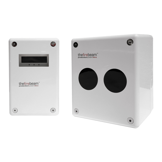
- Page 4 installing and commissioning step one. mounting the head screw the head backing plate to the wall - always try to use as sturdy location as possible, such as brick or major structural steels (avoid mounting to outer metal cladding etc) wire into system as required 2 knock outs are provided See generic wiring diagram on...
- Page 5 generic wiring configuration switch 4 on all rest off to fire panel to controller BROWN + supply (10.2-30 Vdc) FIRE and EOL BLUE - supply (return) components as specified by BLACK zone + the panel manufacturer GREY zone - GREEN earth (screen) Supply Voltage 12Vdc to 24 Vdc +25% -15%...
- Page 6 COVER it if in place already! 2. power up the unit - you will see then the screen will default to 3.
- Page 7 7. signal power starts at 10% and the receiver sensitivity starts at 5% and automatically increases until a received signal from the blank wall without the reflector of between 5 and 7% is achieved, it will then stop received signal if you are covering a distance of over 50 meters you should be...
- Page 8 place or uncover the reflector on the blank wall directly opposite the beam head with a clear path though obstructions such as girders etc. It is important that there is a clear line of vision between the reflector and any obstruction -the beam head must see at least 200mm of clear wall around the reflec- tor to enable successful auto alignment.
- Page 9 40 steps = 1 degree of movement beam head reflector Adjustments can now be made to the axis by using the left(x-), right(x+), up(y+), down(y-) keys. Looking at the reflector this will move the beam across the reflector like so (40 steps = 1degree) (you can hold the key down for faster increments) in the example above moving the...
- Page 10 1. a filter test for ‘Fire’ place the filter provided over the eyes of the firebeam. having done this (after 10 seconds) the...
- Page 11 screen menu system issue 0026-02 NORMAL FIRE FAULT ERROR ALIGN beam head is comms performing a self press enter / menu to enter re-alignment menu system procedure to enter sub menus to decrease to increase default 35% adjustable between 25% and 50% shows ( ) when updating to exit sub menus...
- Page 12 to enter sub menus view amount of internal gain made to compensate for dirt build up on beam lenses -128% to +128% back to exit sub menus counts events since alignment or reset 0-255 to test beam press enter - the power will slowly drop as can be seen in the dropping air quality.
- Page 13 to enter sub menus make adjustments by using the left, right, up down keys (this moves the beam in these directions across the face of the reflector- with your back to the beam) pre- alignment is the first stage of alignment - this should only be used without the reflector...
- Page 14 if the beam is obstructed during auto alignment the alignment will be aborted press back to return to auto alignment and enter to resume auto-alignment once alignment is complete you will see the screen below press back to return to the main screen...
- Page 15 ( ) when updating shows temperature at beam head screen used by The Fire Beam help desk screen used by The Fire Beam help desk software versions for the head and controller...
- Page 16 Rating 2A @ 30 VDC Operational Specifications: Normal Condition: Protection Range: Obscuration level is above the Alarm sensitivity level FIREBEAM. Controller Status – NORMAL Standard Product 5 to 40 metres Controller Green Flashing LED 1 Second 40KIT80. Mid-Range Reflector Kit 40 to 80 metres Programmable on/off 80KIT100.
Need help?
Do you have a question about the firebeam and is the answer not in the manual?
Questions and answers