Advertisement
User's Manual
O
Safety System
2
NOTE 1: Always test your set, BEFORE INSTALLATION!
The different sets are delivered pre-connected in the package.
Be aware! During the test a very loud sound will be emitted from the horn.
The test procedure is described in chapter 3.1 in this manual.
NOTE 2: Remember to perform a startup calibration when the system is installed.
The calibration procedure is described in chapter 4 in this manual.
Advertisement
Table of Contents

Subscribe to Our Youtube Channel
Related Manuals for LogiCO2 O2

Summary of Contents for LogiCO2 O2
- Page 1 User’s Manual Safety System NOTE 1: Always test your set, BEFORE INSTALLATION! The different sets are delivered pre-connected in the package. Be aware! During the test a very loud sound will be emitted from the horn. The test procedure is described in chapter 3.1 in this manual. NOTE 2: Remember to perform a startup calibration when the system is installed.
- Page 2 Horn/Strobe LED, General information 13.1 Power supply control 8.1 General Description 13.2 Central Unit check 8.2 Horn/Strobe, Warning Sign 13.3 O2 Values displayed on the Central Unit 8.3 Horn/Strobe LED, Specifications 13.4 Mk9 O2 Sensor check 13.5 Installation Record 14. Warranty...
- Page 3 It is not allowed to use the O2 sensor in the area if the oxygen is not led out. The LogiCO2´s O2 Safety Systems measures the O2 concentration in a confined space environment and provides alerts/alarms in the event that O2 levels in that space reaches the pre-set alarm levels.
- Page 4 Central Unit O2 Sensors If a sensor detects a low or high O2 level, the O2 sensor alerts via sound and light and remotely connected warning lamps, horns or horn/strobes will be activated. The central unit will alert with sound and display which sensor that has detected a low or high O2 level. A properly installed system will begin to detect O2 levels when powered on, after a self-diagnostics program has been made by the system.
- Page 5 This makes it easy to disconnect the power to the system, if needed. It is very important to be aware that the O2 Safety System does not function if disconnected from power mains.
- Page 6 Correct placement of the O2 Sensor The O2 sensor should be placed in the room where there is a risk for unsafe oxygen concentration – this would be at the distribution points of the nitrogen, nitrogen generator or nitrogen tank as well as mixed gas with nitrogen.
- Page 7 2-2.4 m / 80-96" 1. The horn/strobe/s must be installed on the wall above the O2 sensor, approximately 2-2.4 m/80-96 inches (as per NFPA 72) above the floor, clearly visible from any entrance of the area being monitored. It is recommended that a second horn/strobe be placed OUTSIDE the area being monitored, preferably placed over the door/s leading to the monitored area.
-
Page 8: Connection Of The Power Supply
Installation and connection of the cables Blue The different units are connected to each other by cables. The blue marked cable is used for signalisation (horn/strobe, warning beacon and remote control box). The red marked cable is for communication and power. Please observe, all cables have splitters at the end to facilitate extended cable lengths. -
Page 9: Startup Calibration
AUTO-CAL must be deactivated by setting the DIP-switch number 6 (on the printed circuit board) in up position. If you wish to use the alarm function for high levels of O2, for example an alarm at 23%, the automatic calibration does also need to be deactivated. -
Page 10: Connection Diagram
Possibility to expand with up to four Mk9 O2 Sensors or up to eight Mk9/Mk10/Mk90 CO2 Sensors Please note: A separate installation manual is provided with each extra O2 sensor kit explaining the simple installation process for adding additional sensors to an existing set. - Page 11 Central Unit: ALARM! DO NOT ENTER the risk zone. • The red diode is ON TAKE PRECAUTIONS Evacuate the area if O2 level is • Constant sound signal Low concentration of O2 under 19.5%. Display: • Sensor number, O2 % and...
-
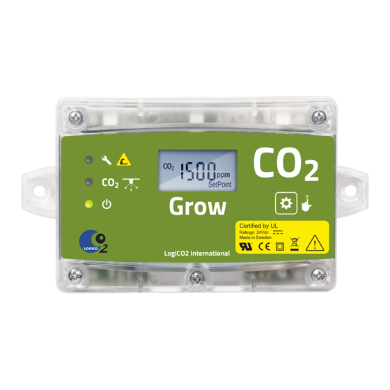
Page 12: General Description
General Description The sensor is an O2 sensor with display that is used to monitor the O2 levels of a confined space. This unit can be connected to a Central Unit or to an existing Mk9 CO2 System for full functionality. - Page 13 Alarm. Ambient O2 concentration level is under or over the alarm constant sound signal settings. The display on the O2 sensor will show the current O2 level and the information text: “EVACUATE AREA: Very critical O2 level!”. If the O2 level is under 19.5%, evacuate the area.
- Page 14 Mk9 O2 Sensor, Internal layout 1 2 3 4 5 6 7 O2 Sensor Function/Indication 1. DIP-switch ID settings 2. LED yellow Fault 3. LED red Alarm 4. LED green Power ON 5. Buzzer High-Alarm 6. Display Measurement and alarm information...
-
Page 15: Alarm Levels
Mk9 O2 Sensor, DIP-switch settings ID-address 1-4: ID- address Dip1 Dip2 1 2 3 4 5 6 7 1 2 3 4 5 6 7 1 2 3 4 5 6 7 1 2 3 4 5 6 7 Alarm levels:... - Page 16 Operation O2 concentration Normal view In normal view, the displays shows: O2 Level: 20.6% The current O2 concentration in %. Also, the A-ALARM trig A-ALARM: <19.5% >23.0% level and the B-ALARM trig level. These levels can be the same B-ALARM: <19.5% >23.0%...
- Page 17 If no further actions is performed for 1 minute, in Calibration Press the button to start mode, the O2 Sensor will go back to Service Mode One. the calibration c. The instructions in the display will say Push the button to start the calibration.
- Page 18 Mk9 O2 Sensor, Specifications Power supply: 24V DC Power consumption: <30 mA Wiring connections: RJ 45 Digital interface: RS485 serial port MODBUS Outputs: 2 x transistor output 24V DC, Min 1 mA Display: Graphical 128x64, backlit Acoustic signal-strength: 76 dBa (1m) max.
- Page 19 The horn/strobe is equipped with a pre-wired cable for connection to the O2 Safety System. The horn/strobe is power supplied from the O2 sensor. Horn/Strobe LED is a loud warning horn (110 dB/1 m) and high intensity strobe (115 cd).
- Page 20 Buzzer General Description The Central Unit has a display that is used to monitor and control a O2 Safety System with up to four sensors. The central unit is multi-lingual and it displays information text for all alarm and error conditions.
- Page 21 System fault indicator Removal of the Mk9 unit cover If the cover of the Mk9 central unit or the O2 sensor needs to be removed please observe the following order of screw reassambling. Note! When remounting the cover, be careful not to damage the reset button.
-
Page 22: Central Unit
Mk9 Central Unit, Internal layout Central Unit Function/Indication 1. DIP-switch Setting number of connected O2 sensors 2. LED yellow Fault 3. LED red Alarm 4. LED green Power ON 5. Buzzer Alarm 6. Display Measurement and alarm information 7. Mute/Reset/Test button Mute/Reset/Test button 8. -
Page 23: Dip Switch Settings
Dip 1-3. NOTE! Dip 4-8 is not in use and must be placed in “OFF” position It is possible to expand the system with up to four O2 sensors, or four O2 sensors and four CO2 sensors or up to eight CO2 sensors. - Page 24 Software version Cycle/Start-up ID CO2 LogiCO2 Central unit FW: 1420* Heating... *FW = Firmware version Normal display information, one O2 sensor connected: One O2 sensor is attached ID CO2 20.9% Display information during O2 alarm mode: O2 Alarm ID CO2 16.0%...
- Page 25 O2-measuring fault. Sensor error! Internal fault in O2-Sensor. Lost sensor! Communication error. Check red cabling and connectors. Check affected O2 Sensors ID- number. 9.13 Mk9 Central Unit, Warning Sign The sign for the Mk9 central unit should be mounted in a permanent way next to or above the unit.
-
Page 26: Service And Maintenance
Since this is a safety product we recommend that a function check be performed on the O2 Safety System by a qualified professional service agent at least once every year. -
Page 27: Power Supply Control
O2 alarm, should be registered on the “What to do” sign. When the central unit is running properly, the green diode (ON) is ON, and the screen should display the O2 levels of the O2 sensor or sensors that are connected. - Page 28 O2 Values displayed on the Central Unit When the system is running properly, the O2 level measured by each sensor is displayed in % (actual value). The values are displayed on the second line of the display. The first character displayed is the sensor ID and the value is displayed after.
- Page 29 Is there a O2 warning sign mounted next to the horn/strobe, with a telephone number to the service provider? Is the O2 warning sign next to the horn/strobe or warning lamp mounted in a permanent way? Is a horn/strobe installed above the sensor at a height of 2.0-2.4 m/80-96 inches?
-
Page 30: Installation Record
Is the horn/strobe mounted at a height of 2.0-2.4 m/80-96 inches so that the staff can see it without any obstructions in the way? Is there a O2 warning sign mounted next to the horn/strobe, with a telephone number to the service provider? Is the O2 warning sign next to the horn/strobe mounted in a permanent way? Is a horn/strobe installed above the sensor at a height of 2.0-2.4 m/80-96 inches? -
Page 31: Warranty
Warranty Warranty Policy LogiCO2 warrants to the Purchaser of the O2 Safety System equipment for two years from the installation date that said equipment shall be free from any defects in workmanship and materials. Purchaser agrees that as a pre condition to any LogiCO2 liability hereunder, Purchaser or its appointed agents shall fully inspect all goods immediately upon delivery and shall give LogiCO2 written notice of any claim or defect within ten (10) days after discovery of such defect. -
Page 32: Contact Information
For parts or service contact your local authorized supplier or equipment service agent. Company: ..................................... Phone: ....................................Place company stamp or sticker here Manufactured by: LogiCO2 International AB Box 9097 E-mail: info@logico2.com 400 92 Gothenburg, Sweden Web: www.logico2.com © 2020-03-05 R1.5 LogiCO2 HFE1109 EN...
Need help?
Do you have a question about the O2 and is the answer not in the manual?
Questions and answers