Table of Contents
Advertisement
Quick Links
Manfred Weber
Metra Mess- und Frequenztechnik in Radebeul e.K.
D-01445 Radebeul
Tel. +49-351-836 2191 Fax +49-351-836 2940 Email: Info@MMF.de
Instruction Manual
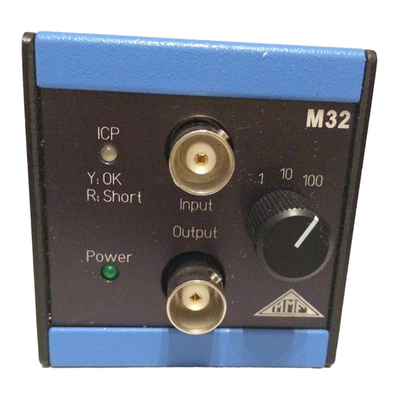
IEPE Conditioning Module M32
Application
The IEPE Conditioning Module M32 is a signal conditioner for transducers with IEPE compatible output. It
provides the necessary power supply for the electronic circuit of the sensor. The unit features 3 gain ranges
and a plug-in low pass filter. The M32 can be used as a front end for PC based data acquisition systems. It
can be combined with the IEPE Supply Module M28. The M32 is suited for both benchtop applications and
Din Rail Attachment in switch cabinets. The wide supply voltage range of the M32 allows power supply from
external batteries, from the available mains plug adapter or from an industrial 24 VDC supply.
What is IEPE?
IEPE is a well-established standard for the output of piezoelectric transducers and microphones. It stands for
"Integrated Electronics Piezo Electric". Other brand names for the same principle are ICP
tron
®
, Piezotron
®
etc. The integrated circuit of the sensor transforms the charge signal of the piezo-ceramic
sensing element, with its very high impedance and high EMI sensitivity, into a voltage signal with low im -
pedance.
A special feature of the IEPE electronics is that power supply and measuring signal are transmitted via the
same cable. So, an IEPE transducer requires, like a transducer with charge output, only one single-ended
shielded cable.
Figure 1 shows the principle circuit diagram. The integrated sensor electronics is supplied with constant cur -
rent. This should not be confused with a 4-20 mA current loop. The constant current I
nal cable of the sensor. A de-coupling capacitor keeps DC components away from the signal conditioning
circuit.
The constant current supply and de-coupling capacitor are part of the M32.
IEPE Transducer
Integral electronics
Q
Piezo ceramics
Figure 1: IEPE principle and functional diagram of the M32
Meißner Str. 58
U
Coaxial cable,
> 100 m
U
offset
+u
sensor
Internet: www.MMF.de
M32
U = 24VDC
s
I
const
= 4mA
Lowpass
Amplifier
module
G =
1/10/100
LED-
sensor
indicator
I
constant supply current from M32
const
U
DC supply voltage of current source in M32
s
®
, Isotron
is fed into the sig-
const
Instrument
Buffer
®
, Delta-
Advertisement
Table of Contents

Summary of Contents for MMF M32
- Page 1 The unit features 3 gain ranges and a plug-in low pass filter. The M32 can be used as a front end for PC based data acquisition systems. It can be combined with the IEPE Supply Module M28.
- Page 2 (24 VDC with the M32). Figure 2 shows the dynamic range of the transducer. The output of the M32 is free of DC components. It provides the unaltered AC sensor output signal.
- Page 3 The M32 requires for operation a supply voltage between 5 and 26 VDC. It can be powered, for example, by: · Industrial 24 VDC supplies · The optionally available mains plug adapters PS500 (for one M32) and PS1000 (for up to 3 units M32) ·...
- Page 4 M32 PS1000: mains plug adapter for 100 .. 240 VAC; 12 VDC / 1000 mA sufficient for up to 3 units M32 M28+32DIN: 35 mm DIN rail adapter -10 .. 55 ー C; 95 % relative humidity; no condensation...
Need help?
Do you have a question about the M32 and is the answer not in the manual?
Questions and answers