Table of Contents
Advertisement
Advertisement
Table of Contents

Related Manuals for Baelz Automatic BA 373-E45

Summary of Contents for Baelz Automatic BA 373-E45
- Page 1 Operating Instructions BA 373-E45 Motorized Linear Actuator baelz 373-E45 Technical specifi cations subject to change without notice Copyright according to ISO 16016 W. Baelz & Sohn GmbH & Co. · Koepffstrasse 5 · 74076 Heilbronn · Germany · www.baelz.de Seite | Page...
-
Page 2: Table Of Contents
Motorized Linear Actuator baelz 373-E45 Table of Contents 1. SAFETY 1.1 Intended use 1.2 Instructions for the operator 1.3 Personnel 1.4 Before starting work 1.5 During operation 1.5.1 Transport, installation and assembly 1.5.2 Maintenance and repair 1.6 Working environment 2. PRODUCT DESCRIPTION 2.1 Identification 1.7 Motorized linear actuator 2.2 Technical Specifications 2.4 Accessories and options 2.3 Type name 2.5 Operating conditions 3. - Page 3 Motorized Linear Actuator baelz 373-E45 7. FITTING THE 7020A DIGITAL POSITIONER 8. DIGITAL POSITIONER 7020A 8.1 Intended use 8.2 Operational modes and operating options 8.2.1 Standard operation using DIP switches 8.2.2 Standard operation using Modbus VT100 or direct addressing 8.2.3 Modbus mode 8.2.4 Normal and safety modes 8.2.4.1 Safety mode: freeze protection and excessive temperature 8.2.5 3-point control with a continuous output signal 8.3 Wiring diagrams and allocation of connection terminals 8.3.1 Wiring diagram 8.3.2 Allocation of connection terminals 8.4 Configuration of the DIP switches 8.4.1 Details on DIP switches 8.5 Commissioning 8.5.1 Quick start guide...
-
Page 4: Safety
Motorized Linear Actuator baelz 373-E45 1. SAFETY Read these operating instructions, in particular the following safety instructions, carefully before installation and operation. Beware Potentially hazardous situation that could result in minor injury. Beware Also indicates a hazard that may result in property damage. Caution Potentially harmful situation in which the product or an object in its Caution vicinity may be damaged. Danger Imminent danger of death or serious injury. Danger Warning Potentially hazardous situation that may result in death or serious injury. Warning Tip: Application instructions and other useful information. 1.1 Intended use Baelz 373-E45 motorized linear actuators are controlled by three-point control or constant control in combination the digital positioner baelz 7020A. The linear actuators of the series described in this document are intended for the stroke adjustment of valves. To ensure their intended use, make sure that the above type identification complies with the nameplate of the linear actuators before starting any activities. The actual technical specifications of the linear actuators and the power supply requirements are the specifications indicated on the nameplate. Any use other than the intended use mentioned above, different tasks, and operation with other power sources than those permitted, is considered to be improper use. In case of improper use, the operator shall be solely liable for the risk presented to persons and the device as well as other property! Intended use also includes compliance with accident prevention and DIN VDE regulations as well as safe working practices for all measures described in these operating instructions, taking into account the usual technical regulations. -
Page 5: Personnel
Motorized Linear Actuator baelz 373-E45 1.3 Personnel Only qualified personnel may work on this linear actuator or in its vicinity. Qualified persons are deemed to be persons who are familiar with the installation, assembly, commissioning and operation or maintenance of the actuators and have the appropriate qualifications for their job. Necessary or prescribed qualifications include, but are not limited to: ● Training / instruction and the authorization to switch electric circuits and devices / systems on and off in accordance with EN 60204 (DIN VDE 0100 / 0113) and the technical safety standards ● Training or instruction in the care and use of appropriate safety and work protection equipment in accordance with safety technology standards. ● First aid training. Work in a safe manner and avoid any operation that would endanger the safety of persons or damage the linear actuator or other property in any way. 1.4 Before starting work Before carrying out any work, check whether the types specified here correspond to the information on the name plate of the actuator: baelz 373-E45 1.5 During operation Safe operation is only possible if transport, storage, assembly, operation and maintenance is carried out in a safe, proper and professional manner. 1.5.1 Transport, installation and assembly Observe the general installation and safety regulations for heating, ventilation, air conditioning and piping systems. Use tools only for their intended purpose. Wear the required personal and other protective equipment. -
Page 6: Product Description
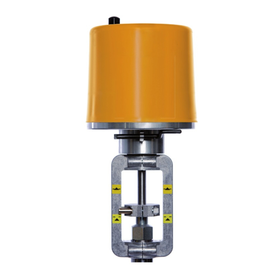
Motorized Linear Actuator baelz 373-E45 2. PRODUCT DESCRIPTION 2.1 Identification Each actuator has a nameplate showing specifications regarding the maximum operating conditions of the device and a unique, order-related serial number (F no.). Fig. 1: Baelz nameplate for motorized actuators 1.7 Motorized linear actuator The baelz 373-E45 is a motorized linear actuator with load-dependent limit switches for flow control applications. The actuators are designed for highly accurate positioning in an industrial environment. They come complete with a manual adjustment device and a wide range of options and additional extras are available. 2.2 Technical Specifications Table 1. Technical Specifications, baelz 373-E45 Actuating force Positioning speed mm/min Power consumption (230 V) VA Nominal current (230 V) -
Page 7: Accessories And Options
Motorized Linear Actuator baelz 373-E45 2.4 Accessories and options Table 2. Options for Actuators Two additional limit switches for signalling end positions or intermediate positions, freely adjustable, max. 250 V AC, rating for resistive load max. 5 A, for inductive load max. 3 A 2EZ-Fg 200 Ω / 1 kΩ / 5 kΩ potentiometer, linearity error ≤ 0.5%, max. 1.5 W, contact current 30 mA, stroke reduced by [%ohm x actual stroke/44] mm, depending on valve stroke Digital positioner for actuator control, self adapting 1 input signal: 0(2)…10 V, 0(4)…20 mA or (3-point) 7020A 2 output signals: 0(2)…10 V and 0(4)…20 mA 1 digital input, 2 relays for feedback on end or intermediate positions, Interface RS485 Modbus RTU, incl. 5 kΩ potentiometer Heating resistor with thermoswitch against moisture with automatic temperature regulation, max. 15 Watts, supply voltage 24, 115, 230 V 50/60 Hz 2.3 Type name baelz 373 motorized linear actuator actuator type thrust positioning speed yoke type 2.5 Operating conditions In case of extreme variations in ambient temperature and high humidity levels, installation of a heating resistor is recommended to minimise condensation in the actuator. -
Page 8: Assembly
Motorized Linear Actuator baelz 373-E45 4. ASSEMBLY Make sure that the specifications on the nameplate correspond to those in the order documents! Attention 4.1 Fitting position When fitting with the connecting rod in horizontal position, fit the linear actuator such that the sides of the yoke are positioned one above the other in the vertical plane. Risk of damage if no valve is fitted to actuator! Caution Caution: ●... -
Page 9: Assembly With The Valve
Motorized Linear Actuator baelz 373-E45 4.2 Assembly with the valve Prior to assembly, check that: ● the operating conditions comply to the specifications of the linear actuator. ● the valve is complete (yoke on actuator or on valve). ● the connections on valve and actuator match. The linear actuator is supplied with the spindle retracted. A slight adjustment for fitting of the coupling can be carried out by turning the spindle. The following dimensions must be adhered to, otherwise damage to the actuator can ensue. Attention Keep the spindle within the given stroke range to avoid damage to the actuator! Y = max. 88,5 mm X = max. 188 mm min. 46,5 mm min. -
Page 10: Principle Of Operation
Motorized Linear Actuator baelz 373-E45 4.3 Principle of operation Motorized linear actuators to operate control valves for fl ow regulation applications in control and process technology. The self-locking threaded spindle/spindle nut is driven by an electric motor via a gearbox. This converts the rotary movement into a linear movement. Load- dependent limit switches dictate the end positions 4.3.1 Manual adjustment Manual adjustment may only be carried out when the motor is not in motion. For the adjustment, unscrew the cap nut from the top of the cover, remove the hand crank from the bracket on the bottom of the actuator housing and insert it into the tube in the top of the cover. Turn the crank handle using gentle pressure. W. Baelz & Sohn GmbH & Co. · Koepffstrasse 5 · 74076 Heilbronn · Germany · www.baelz.de Seite | Page 10 |... -
Page 11: Electrical Connection
Motorized Linear Actuator baelz 373-E45 4.4 Electrical connection Risk of electric shock! Danger Use an appropriate power supply to ensure that no hazardous voltage can enter the device during normal operation or in the event of a system failure or defective system components. -
Page 12: Commissioning
Motorized Linear Actuator baelz 373-E45 5. COMMISSIONING Compare the thrust of the actuator and the set travel with the valve specifications. Overloading can result in severe damage to the valve. Pay attention to moving parts during fitting and adjustment. Risk of injury and substantial material damage. Actuators which are supplied fitted with a valve are set to the appropriate valve stroke length. When an actuator with a 7020A digital positioner is fitted to a valve, an initialization run must be carried out to set up the Attention actuator according to the valve type. -
Page 13: Fitting The Potentiometer Assembly
Motorized Linear Actuator baelz 373-E45 6. FITTING THE POTENTIOMETER ASSEMBLY Disconnect actuator from power supply before starting work! Danger 6.1 Installing the potentiometer assembly Fit the distance sleeve (4) onto the threaded end of the connecting rod and tighten. Place the laminate washer (2) over the threaded end onto the self-locking nut. Insert the position detector for the potentiometer assembly (3) ensuring it engages in the slot provided on the toothed rod. Screw another laminate washer (2) and self-locking nut (1) onto the threaded insert and slightly tighten the nut The potentiometer assembly can then be fitted (1) and secured with the screws provided (2) Fig. 4: Fitting the potentiometer assembly W. Baelz & Sohn GmbH & Co. · Koepffstrasse 5 · 74076 Heilbronn · Germany · www.baelz.de Seite | Page 13 |... -
Page 14: Adjusting The Potentiometer Assembly
Motorized Linear Actuator baelz 373-E45 6.2 Adjusting the potentiometer assembly 1. The potentiometer can be set to the defined zero point using the screw slot on the rear (for normal mode clockwise up to the mechanical stop). For valve stroke < 44 mm, note that for reverse mode, the potentiometer must be turned to the new zero point (mechanical stop opposite). For this adjustment the actuator spindle must be in the correct end position: Normal mode: zero point = spindle extended --> potentiometer fully clockwise Reverse mode: zero point = spindle retracted --> potentiometer fully anticlockwise 2. The additional limit switches can be adjusted by loosening and retightening the knurled nut and setting the contact washers to the desired positon. Fig. 5: Adjusting the potentiometer assembly W. Baelz & Sohn GmbH & Co. · Koepffstrasse 5 · 74076 Heilbronn · Germany · www.baelz.de Seite | Page 14 |... -
Page 15: Fitting The 7020A Digital Positioner
Motorized Linear Actuator baelz 373-E45 7. FITTING THE 7020A DIGITAL POSITIONER Disconnect actuator from power supply before starting work! Danger These instructions apply, given that the potentiometer assembly has been correctly fitted as described in section 6.1. ● Remove the extension and the brass sleeve. ● Insert the M4 x 5 mm screw into the limit switch plate, but do not tighten it. Put the bracket in place. Now tighten the screw. W. Baelz & Sohn GmbH & Co. · Koepffstrasse 5 · 74076 Heilbronn · Germany · www.baelz.de Seite | Page 15 |... - Page 16 Motorized Linear Actuator baelz 373-E45 ● Before fitting the adaptor panel, the nameplate must be stuck to the underside. If the digital positioner board ist replaced, this nameplate must also be changed. ● Place the 4 click-fit spacer connectors on the adaptor panel. ● Fit the adaptor panel over the threaded end of the extension so that it rests on the bracket. W. Baelz & Sohn GmbH & Co. · Koepffstrasse 5 · 74076 Heilbronn · Germany · www.baelz.de Seite | Page 16 |...
- Page 17 Motorized Linear Actuator baelz 373-E45 ● Fit the spacer sleeve onto the thread and screw the extension on. ● Adjust the adapter panel on the bracket so that the countersunk hole and the hole in the bracket are aligned. Insert the plastic screws and fit and tighten the nuts on the underside of the bracket. ● Mount the digital positioner board onto the click-fit spacer connectors. The transformer should be on the same side as the potentiometer. W. Baelz & Sohn GmbH & Co. · Koepffstrasse 5 · 74076 Heilbronn · Germany · www.baelz.de Seite | Page 17 |...
- Page 18 Motorized Linear Actuator baelz 373-E45 ● Wire up the digital positioner board with the motor and the potentiometer according to the wiring diagram 7020A, Fig. 9, page 21. ● Stick the wiring diagram to the inside of the actuator cover. Please note the digital positioner type - in this case "7020A" - on the actuator nameplate under "X:". W. Baelz & Sohn GmbH & Co. · Koepffstrasse 5 · 74076 Heilbronn · Germany · www.baelz.de Seite | Page 18 |...
-
Page 19: Digital Positioner 7020A
Motorized Linear Actuator baelz 373-E45 8. DIGITAL POSITIONER 7020A 8.1 Intended use The digital positioner baelz 7020A controls the actuator according to the value of the control signal: 0(2)-10 V, 0(4)-20 mA To ensure use for the purpose intended, check that the above type identification corresponds to the nameplate on the positioner before starting any activities. The technical specifications of the positioner and the power supply requirements are the indicated on the name plate. Any use other than the intended use stated above, use for different tasks, and operation with other power sources than those permitted, is considered to be improper use. In case of improper use, the operator shall be solely liable for the risk presented to persons and to the device as well as to other property! The intended use also comprises compliance with the accident prevention regulations and the DIN VDE standards of the German Institute for Standardization and the Association for Electrical, Electronic & Information Technologies. It also implies working in accordance with the safety requirements when performing all activities described in these operating instructions, under consideration of general technical rules and regulations. 8.2 Operational modes and operating options Tip: For further information and additional functions, see baelz 7020 operating instructions. 8.2.1 Standard operation using DIP switches The DIP switches can be used to carry out standard configurations and operations (see section 8.4... -
Page 20: Normal And Safety Modes
Motorized Linear Actuator baelz 373-E45 8.2.4 Normal and safety modes In normal mode the position of the valve is controlled by the set value at analogue input AI2. The N↔S switch shown in the picture on the right is set to normal mode (N). In normal mode, no external control systems can be connected to terminals 12 and 14. Fig. 6: N↔S-switch 8.2.4.1 Safety mode: freeze protection and excessive temperature In safety mode the actuator can be sent to a safe position (extended / retracted, depending on the direction of action of the valve) in case of failure or malfunctioning of the microcontroller. To operate the Baelz 7020A in connection with an external freeze protection and/or excessive temperature thermostat, set the N↔S switch to safety mode (S). Connect the freeze protection and/or excessive temperature thermostat according to desired function and priority. Be sure to take the direction of action into account! See wiring diagrams in the baelz 7020 operating instructions. 8.2.5 3-point control with a continuous output signal 1. -
Page 21: Allocation Of Connection Terminals
Motorized Linear Actuator baelz 373-E45 Fig. 9: Wiring diagram with digital positioner baelz 7020A 8.3.2 Allocation of connection terminals Terminal Allocation Notes 2, 3 supply terminals See wiring diagram for correct allocation. 4, 5, 12, 14 Can be allocated to an For external control, the overriding external control N↔S switch must be set system (freeze protection, to „S“ (safety mode). excessive temperatures). 20, 22 Digital input for a switch used to select between two conditions,... -
Page 22: Configuration Of The Dip Switches
Motorized Linear Actuator baelz 373-E45 8.4 Configuration of the DIP switches The factory setting of the DIP switches is position 0, as shown. Switch Function Position 1 "ON" Position 0 DIP 1 Set value input: voltage, V or current, mA? current, mA voltage, V DIP 2 Set value input starting at 0 V / 0 mA or 2-10 V / 4-20 mA 0-10 V / 0-20 mA 2 V / 4 mA? DIP 3 Analogue output starting at 0 V / 0mA or... -
Page 23: Details On Dip Switches
Motorized Linear Actuator baelz 373-E45 8.4.1 Details on DIP switches DIP1 and DIP2: are interpreted together: DIP1: 0 = voltage → DIP2: 0 = 0-10 V or 1 = 2-10 V. DIP1: 1 = current → DIP2: 0 = 0-20 mA or 1 = 4-20 mA. Either a voltage source can be connected to the U-terminal or a current source to the I-terminal. Never connect both at the same time. Attention DIP3: DIP switch 3 configures the analogue outputs AO1 and AO2 (see wiring diagram, Fig. 9, page... - Page 24 Motorized Linear Actuator baelz 373-E45 [0 0 0] [0 1 1]* [1 1 1]* open open open open open shut shut shut shut shut 100 % 100 % 100 % input signal 11-point Split range Split range Linear Inverse linear characteristic split 50 % split 33 % Fig. 11: Graphical illustration of selection of functions by DIP switches 7, 8 & 9 DIP10: An actuator characteristic can be used indirectly to change a valve characteristic. If, for example, the valve has an equal percentage characteristic, an inverse equal percentage...
-
Page 25: Commissioning
Motorized Linear Actuator baelz 373-E45 8.5 Commissioning 8.5.1 Quick start guide ↑ 1. Set DIP switches 2. Connect to supply 3. Start initialization run 8.5.2 Initialization run If the unit is not initialized, the green LED fl ashes. The red LED is lit when the position of the potentiometer is not ideal for an initialization run. (See section 8.5.3 for meaning of LED signals.) An initialization run can still be carried out, but it will take approx. 1x valve travel time longer. During a successful initialization run, the valve is moved to both of its end positions. The potentiometer and the position of the valve are synchronized and values for valve travel time and switching hysteresis are determined. Switch DIP switch 12 from 0 to 1 to start an initialization run. The red LED is lit during initialization. When initialization has been successfully completed, only the green LED is lit. For error signals see table in section "Errors after an initilization run", page 27 As long as DIP switch 12 is set to 1, errors and alarms occurring during normal positioner operation will not be shown. This enables errors occurring during initialization to be distinguished from errors during normal positioner operation. Switch DIP 12 back to 0 after the initialization run to show any errors occurring in normal positioner operation on the red LED. (After the fi rst initialization run (unit not previously initialized), the unit moves to the 50% position upon completion of initialization. As soon as DIP 12 is set to 0, the baelz 7020A will follow the set value signal at analogue input 2.) W. -
Page 26: Meaning Of Led Signals
Motorized Linear Actuator baelz 373-E45 8.5.3 Meaning of LED signals green LED red LED Meaning signal signal green off Unit is switched off. red off green off Initialization run in progress. red on green Unit is not initialized. Potentiometer in ideal position for initialization run (between 7.5 and flashing 17.5%). red off green Unit is not initialized. Potentiometer not in ideal position for initialization run. flashing Initialization still possible. (If the red LED is flickering, the position of the potentiometer is at the edge of the optimal range and therefore OK.) red on green Error during initialization. Unit is not initialized. The flashing red LED shows the number of and red the error code: 3 flashes, interval, 3 flashes, interval → error code 3. See also section 8.6.1. flashing green on Unit is initialized. No errors. -
Page 27: Errors
Motorized Linear Actuator baelz 373-E45 8.6 Errors 8.6.1 Errors after an initialization run Following a successful initialization run, only the green LED is lit. If the red LED is flashing, this indicates an error following an unsuccessful initialization run. The first error to occur during initialization is shown. If the green LED is lit, the unit had already been initialized before the current initialization run. If the green LED is flashing, the unit had not been successfully initialized previously. The red LED shows errors occuring during initialization as follows: Error code 1: interval interval etc. Error code 2: interval interval etc. etc. up to ... Error code 8: interval interval etc.. Error code Error Corrective action Invalid status of initialization run. Possible Remove source of interference. 1 → 1 x cause: EMI (electromagnetic interference). -
Page 28: Errors During Normal Positioner Operation
Motorized Linear Actuator baelz 373-E45 8.6.2 Errors during normal positioner operation The green LED is lit during normal positioner operation. A flashing red LED shows an error during normal positioner operation. For this, DIP switch 12 must be set to 0. The red LED indicates errors during normal positioner operation as follows: = long flash, = short flash) Error code 1: interval interval etc. Error code 2: interval interval etc. etc. up to ... Error code 6: interval interval etc. Multiple error codes can be displayed simultaneously: Error codes 3 & 5: interval interval The red LED flashes 10 times between intervals (1.6 s), as a maximum of 10 error codes can be allocated. The error codes 7 to 10 are not allocated and are reserved for additional alarms. Error code Error Corrective action Sensor malfunction at analogue input AI1: Check connection terminals 91, 92, 93 No signal from potentiometer. -
Page 29: Technical Specifications
Motorized Linear Actuator baelz 373-E45 8.7 Technical Specifications Table 3. Technical Specifications, baelz 7020A 230 VAC -15 % / +10 %, 50 / 60 Hz, Supply voltage option: 115 VAC 50 / 60 Hz, 24 VAC 50 / 60 Hz Fuse internal 1.6 A/T (slow-blow) Power consumption approx. 5 VA IP rating IP 42 Ambient temperature 0 to 50 °C Transport / storage temp. - 25 to +65 °C Ambient humidity 5 to 90 % relative humidity. (non-condensing) Dimensions WxHxD approx. 105 x 82 x 32 mm DI suppy voltage 24 V DC, Imax = 5 mA 1 configurable using software, Imax 5mA,... -
Page 30: Heating - Retrofitting The Heating Element
Motorized Linear Actuator baelz 373-E45 9. HEATING - RETROFITTING THE HEATING ELEMENT Preparatory measures before fitting: 1. Disconnect actuator from power supply 2. Remove the cap nut from the actuator cover 3. Pull and gently turn cover to remove ● Screw the temperature sensor firmly into the hole by the load-dependent limit switches. Fix the heating element in its place on the cover using the two screws provided. ● Remove the screw from the limit switch board and replace it together with the terminal block. ● Connect both wire ends to terminals (7) and (8). Terminals 7 and 8 are then connected to the electrical supply. Fix wiring with cable ties. W. Baelz & Sohn GmbH & Co. · Koepffstrasse 5 · 74076 Heilbronn · Germany · www.baelz.de Seite | Page 30 |... -
Page 31: Spare Parts
Motorized Linear Actuator baelz 373-E45 10. SPARE PARTS Part no. Description Remarks Mounting plate (complete) 15.20 Circuit board, including motor capacitor (complete) Motor (complete) Cover (complete) (F1653882 and above: new version) 17.4 Cap nut Mounting plate Digital positioner 7020A Fitting material for digital positioner 7020A Extension Crank handle (complete) Flange, complete with connecting rod Potentiometer assembly including 2 limit switches (complete) (F1653882 and above: new version) Potentiometer (complete) (F1653882 and above: new version) Heating element (complete) When ordering accessories or spare parts, please note the specifications on the actuator nameplate for essential information regarding actuator and power supply criteria. Risk of damage to actuator due to incorrect or defective spare parts! Attention All spare parts must comply with the technical requirements as stated by the manufacturer. -
Page 32: Decommisioning And Disposal
Motorized Linear Actuator baelz 373-E45 11. DECOMMISIONING AND DISPOSAL Dispose of the digital positioner in accordance with the relevant, country-specific regulations and laws.. 12. TROUBLESHOOTING If the actuator does not work properly, proceed as follows to correct the problem: 1. Check that the actuator is correctly installed. 2. Check the actuator settings and the specifications on the nameplate. 3. Correct the problems as specified in the checklist (page 33). 4. If the problem cannot be corrected, contact the Baelz service department. 5. If, despite consultation, the issue still cannot be resolved, the device can be returned to Baelz for repair / replacement by arrangement with the service department. Please give the following information when contacting the manufacturer or sending the device in for repair: ●... -
Page 33: Checklist For Operational Malfunctions
Motorized Linear Actuator baelz 373-E45 12.1 Checklist for operational malfunctions Malfunction Cause Action required Power failure Determine the cause and correct the problem. Defective fuse (in control cabinet) Determine the cause and correct the problem, replace the fuse. Linear actuator incorrectly connected Re-connect as specified on circuit diagram (inside cover). Short circuit caused by humidity Determine the cause, dry the linear actuator; if necessary, replace cover seal and screws and/or fit protective Actuator not working cover. Short circuit caused by incorrect connection Connect correctly. Motor winding damage caused, for example, Determine cause, measure current by high voltage or defective electronics data, compare with nameplate and specifications, dismantle linear actuator and return for repair. Voltage drop due to connecting cables being Measure current data with linear too long and / or having insufficient cross- actuator, recalculate connecting section cables and replace as necessary. -
Page 34: Dimensional Drawings
Motorized Linear Actuator baelz 373-E45 13. DIMENSIONAL DRAWINGS Fig. 12: Dimensional drawing Fig. 13: Dimensional drawing baelz E45 with S21 yoke baelz E45 with S21L yoke and spindle Ø 10 mm and spindle Ø 16 mm W. Baelz & Sohn GmbH & Co. · Koepffstrasse 5 · 74076 Heilbronn · Germany · www.baelz.de Seite | Page 34 |... - Page 35 Motorized Linear Actuator baelz 373-E45 Fig. 15: Dimensional drawing Fig. 14: Dimensional drawing baelz E45 with S41C yoke baelz E45 with S41 yoke and spindle Ø 16 mm and spindle Ø 16 mm W. Baelz & Sohn GmbH & Co. · Koepffstrasse 5 · 74076 Heilbronn · Germany · www.baelz.de Seite | Page 35 |...
Need help?
Do you have a question about the BA 373-E45 and is the answer not in the manual?
Questions and answers