
Related Manuals for WEISS HP140T Series

Summary of Contents for WEISS HP140T Series
- Page 1 Installation- and operating manual HP140T Mechanical system documentation TD0037A-EN00-0000-00 980-204018000 / EN 09-2011...
- Page 2 All rights in this document are the copyright of WEISS GmbH. This document may not be copied or reproduced, in whole or in part, without the written permission of WEISS GmbH. This document is only intended for the user of the product described and may not be passed on to third parties, in particular competitors.
-
Page 3: Table Of Contents
Installation prerequisites ................28 5.3. Assembling the Pick & Place ..............29 5.4. Assembly suggestions ................30 5.5. Weiss Tool-Connector ................33 5.6. Installing the safety equipment ..............34 5.7. Instructions on disposal of packaging material ........... 34 Commissioning ....................35 6.1. - Page 4 11. Service and spare parts ..................45 11.1. Ordering spare parts ................... 45 11.2. Spare parts list .................... 45 12. Appendix ......................46 12.1. Index ......................46 12.2. Personal notes .................... 48 Illustration index General view of the Pick & Place .................. 13 Example of a type plate ....................
-
Page 5: Introduction
Introduction 1.1 Definition Introduction Definition Mechanical system documentation Handling device HP140T The Pick & Place is a handling device with direct motor-driven axles. In the following, the Pick & Place will be referred to as "machine". Correct use The machine is a noncomplete machine conforming to Directive 2006/42/EC, Article 1g and 2g. -
Page 6: Ec Declaration
2006/42/EC, Annex II A has been issued. System-dependant documentation In addition to this manual, further documents are required to ensure safe operation of this machine. The specifications stated in these documents are to be observed. For control system by WEISS-GmbH: • Electrical operating manual •... -
Page 7: Operating Manual
Introduction 1.7 Operating manual Operating manual This operating manual is a translation of the original operating manual and is part of the scope of delivery. We reserve the right to undertake modifications resulting from further technological development which diverge from the data and illustrations contained in this operating manual. -
Page 8: Guarantee And Liability
Introduction 1.8 Guarantee and liability 1.7.2 Legend In these manual images, symbols and abbreviations with the following meaning are used for clarity: 1. Marks a numbered list. a) Marks the second level of a numbered list. • Marks a list. ... -
Page 9: Safety
Safety 2.1 Fundamental safety instructions Safety Fundamental safety instructions 2.1.1 Operator‘s obligation to exercise diligence This machine conforms to state-of-the-art technological standards and ensures a maxi- mum level of safety. However, this level of safety can only be attained under operating conditions if all measu- res necessary for this have been taken. -
Page 10: Safety Equipment For The Machine
Safety 2.2 Safety equipment for the machine 2.1.2 Requirements to be met by personnel It is imperative that the following safety instructions be observed during all operations involving the machine. This ensures avoidance of life-threatening injuries, machine damage, other material damage and environmental damage. Personnel must ensure that •... -
Page 11: Residual Hazards
Safety 2.3 Residual hazards The operator is responsible for ensuring that a suitable safety concept is developed and applied for the safe operation of the machine. The operator must take all measures to protect his personnel against injury by the machine. - Page 12 Safety 2.3 Residual hazards Electric shock Power and control connections may still conduct electricity after the machine has been deactivated and is stationary. Energised capacitors inside the servo amplifier may still be charged, despite the power supply being deactivated. Work on electrical equipment should only be realised by skilled electrical personnel and under observance of specifica- tions in the electrical operating manual.
-
Page 13: Product Description
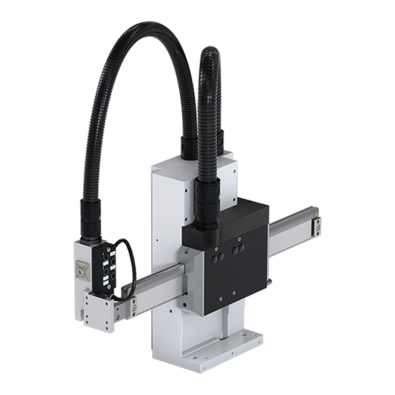
Product description 3.1 Structure Product description Structure The freely programmable Pick & Place HP140T integrates two perpendicular linear axles - the horizontal axle [Y] and the vertical axle [Z] - in a compact housing. All connections are guided through the rear. The operator can add grippers or another device to the horizontal axle [Y]. -
Page 14: Function
Product description 3.2 Function Function The linear motors of the two axles are controlled via amplifiers. High positional accuracy and repeat accuracy is achieved by the integrated magnetic measuring system. The positional accuracy describes the acceptable tolerance of the linear unit for an ope- rating command involving movement to a specified position. -
Page 15: Axle Loads
XX mm Measurement system* sin / cos, 1 encoder Year of construction year XXXX Weight www.weiss-gmbh.de weight XX kg * sinus / cosinus measurement system with pole pitch of 1 mm Fig. 2: Example of a type plate Type Encoder... - Page 16 Product description 3.3 Technical data 3.3.5 Axles Type (Z-Axle) (Y-Axle) Traverse paths Max. 65 / 100 mm Max. 160 / 270 / 300 / 400 mm Acceleration Max. 40 m/s Max. 40 m/s Speed Max. 2.0 m/s Max. 4.0 m/s 10 m/m incremental (sin/cos 1 V System accuracy...
-
Page 17: Dimensions
Product description 3.3 Technical data 3.3.8 Linear motors ID - B&R Description Unit Horizontal motor Vertical motor Electrical Cycle Length [mm] 27,6 28,1 Nominal Voltage (DC) [VDC] Back-EMF Constant (RMS) [V/(m/s)] Nominal Speed [m/s] Maximum Speed [m/s] Stall Force Nominal Force Maximum Force Force Constant [N/A]... -
Page 18: Screw Hole Pattern
Product description 3.3 Technical data 3.3.9.2 Absolut (HP140TDx / HP140TEx) Type AHP 1/90 Voltage supply +5 V Interfaces absolut BISS-C / SSI Incremental signals sin / cos 1 Vss Accuracy measuring system 5 µm (transmitter + tape measure) at 20 °C Storage: -30 °C bis +80 °C Allowable temperature range Operation: +10 °C bis +60 °C... -
Page 19: Adaption Gripper
Product description 3.3 Technical data 3.3.11 Dimensions min. 15 - max. 287 Fig. 5: Dimensions stroke vertical 100 mm stroke horizontal 160 mm Installation- and operating manual Handling device HP140T R09-2011 19/52... -
Page 20: Plug-In Connections
Product description 3.3 Technical data 3.3.12 Hole patterns 3.3.12.1Screw hole pattern 154,5 10 ± 0,05 10P9 120 ± 0,01 Fig. 6: Screw hole pattern stroke horizontal 160 mm Side view base plate Basic housing, HP140T a Pin holes 6H7 b Long holes for M8 bolts Hole pattern for customer base plate 20/52 Installation- and operating manual Handling device HP140T R09-2011... - Page 21 Product description 3.3 Technical data 3.3.12.2Adaption gripper Fig. 7: Adaption gripper Installation- and operating manual Handling device HP140T R09-2011 21/52...
-
Page 22: Electrical Connections
Product description 3.4 Electrical connections Electrical connections Deliveries with electrics package includes the drive controls and the customised electri- cal lines. The connections for the vertical axle are marked red. The connections for the horizontal axle are marked blue. 3.4.1 Plug-in connections Wire-running possibilities X40 - Digital inputs / outputs... -
Page 23: Pneumatic Valve
Product description 3.4 Electrical connections 3.4.3 Connector pin assignment 3.4.3.1 Motors Round plug Name Function Size Motor connection, U 1BEGA125MR13 00 Motor connection, V 000 6 000 Motor connection, W Protective earth Temperature sensor Temperature sensor Brake + (reserve) Brake - (reserve) 3.4.3.2 Encoder incremental D-sub plug Name... -
Page 24: Option With Automatic Lubrication
Product description 3.5 Option with automatic lubrication 3.4.3.4 Control lead D-sub plug Name Function +24 V 24 V supply GND supply 15-pin male Sensor 1 Sensor 3 Valve 2 +24 V 24 V supply GND supply Sensor 2 Sensor 4 Valve 1 Option with automatic lubrication Instead of lubricating nipples, connections [1] for automatic lubrication are provided. -
Page 25: Option With Integrated Pneumatic Valves
Product description 3.6 Option with integrated pneumatic valves Option with integrated pneumatic valves Up to two pneumatic valves [1] for the control of the gripper function can be installed in the housing. The supply of the pneumatic valves with compressed air is realised using a plug-in threaded fitting[2]. -
Page 26: Option With Tool Connector
Product description 3.7 Option with tool connector Option with tool connector The machine can be optionally delivered with a tool connector. With this, the pneumatic and electrical supply up to the gripper is prepared. The tool connector consists of the following components: •... -
Page 27: Transportation
Transportation 4.1 Transportation damage Transportation During transport and storage, devices must be protected from ex- cessive stress (mechanical load, temperature, humidity, rough atmospheric condi- tions). The horizontal track of the HP140T must be protected from exposure to magnetic or metallic objects. Do not bring any external magnets into contact with the horizontal track;... -
Page 28: Installation
Installation 5.1 Safety during installation Installation Safety during installation Injuries caused by incorrect installation. The dimensions of the supporting ground and fastening equipment must sufficient, so that they can withstand the stresses produced during operation. Work should only be assigned to auxiliary personnel by company installation personnel. Injuries caused by sharp-edged machine parts which are still uncovered and acces- sible. -
Page 29: Assembling The Pick & Place
Installation 5.3 Assembling the Pick & Place Assembling the Pick & Place The magnetic measurement system will be destroyed, in case there is contact between the horizontal axles or with magnetized objects. The horizontal axle of the Pick & Place therefore has a protective cover [1], which guards it against damage and exposure to metallic or magnetic objects. -
Page 30: Assembly Suggestions
Installation 5.4 Assembly suggestions 5.3.3 Mounting of attachment parts Regarding the mounting of attachment parts at the housing, the side cover plate of the HP140T can be bored at appropriate positions. The side cover plate needs to be removed from the housing before the bores are made. -
Page 31: Assembly At A Groove
Installation 5.4 Assembly suggestions 5.4.2 Option 2 - firm pinning 1. Bring the Pick & Place to its assembly position. 2. Screw in the two fastening bolts [1], but do not tighten them yet. 3. Drive a dowel pin into each of the three pin holes [2]. 4. -
Page 32: Gripper Front Side
Installation 5.4 Assembly suggestions 5.4.3 Option 3 - Movable via groove 1. Bring the Pick & Place to its assembly position. 2. Screw in the two fastening bolts [1], but do not tighten them yet. 3. Drive a dowel pin into each of the two front pin holes [2]. 4. -
Page 33: Weiss Tool-Connector
Installation 5.5 Weiss Tool-Connector Weiss Tool-Connector 5.5.1 Adaption gripper on front side Fig. 17: Gripper front side 5.5.2 Adaption gripper left Fig. 18: Gripper left Installation- and operating manual Handling device HP140T R09-2011 33/52... -
Page 34: Installing The Safety Equipment
Installation 5.6 Installing the safety equipment 5.5.3 Adaption gripper right Fig. 19: Gripper right Installing the safety equipment Fitting of safety equipment and emergency stop buttons is the responsibility of the opera- tor. The machine may not be operated without safety equipment suitable for the intended purpose. -
Page 35: Commissioning
Commissioning 6.1 Safety during commissioning Commissioning Safety during commissioning Injuries emanating from unexpected activation. Incorrectly-established connections or external influences on electrical equipment can cause unexpected activation of the machine or uncontrolled movement. Ensure that nobody is present in the hazardous zone around the machine. Activate and check all safety equipment and emergency stop circuits prior to commissioning. -
Page 36: Initial Commissioning
Initial commissioning If a Pick & Place is delivered with amplifier and software, the commissioning will be car- ried out via the Weiss Application Software (WAS). Further information on this can be found in the electrical and software documenta- tion for the HP140T. -
Page 37: Operation
Operation 7.1 Safety during operation Operation Safety during operation Risk of injury due to incorrect alteration of operating parameters. Operating parameters should only be changed by authorised persons. Altered operating parameters should be checked in a test. Operating the Pick & Place The machine is designed for integration in other machines, in other incomplete machines or equipment or for connection to these. -
Page 38: Malfunctions
You can contact our Customer Service from Monday to Friday between 08:00 and 17:00 at the Service number +49 (0) 6281 - 5208-0 or at service@weiss-gmbh.de An answering machine will provide you with information outside of the abovementioned hours. 38/52... -
Page 39: Maintenance
Maintenance 9.1 Safety during maintenance Maintenance Safety during maintenance Injuries caused by the power supply and residual energy. All power sources should be deactivated prior to carrying out maintenance work, and secured against unintentional reactivation and marked with a sign indicating that mainte- nance work is in progress. -
Page 40: Maintenance Work
Maintenance 9.2 Maintenance work Maintenance work Maintenance includes tasks for the purpose of: • Inspection • Maintenance • Repair Risk emanating from unexpected activation. There is a risk of unexpected start-up if the power supply has not been deactivated or is inadvertent reactivated. -
Page 41: Maintenance
Move the respective axle about 40 mm by hand during lubrication. The pump stroke for the hand-held grease gun from Weiss is approx. 0.8 cm Fig. 21: Lubricating axles 2. Wipe off leaked excess grease with a soft cloth. -
Page 42: Repair
Repair The operator should not perform any maintenance or repair work on the machine. Should maintenance or repair work become necessary, the customer service of WEISS GmbH is to be contacted. 42/52 Installation- and operating manual Handling device HP140T R09-2011... -
Page 43: Decommissioning / Dismantling / Disposal
Decommissioning / Dismantling / Disposal 10.1 Safety during decommissioning and dismantling Decommissioning / Dismantling / Disposal 10.1 Safety during decommissioning and dismantling Strong magnetic fields Strong magnetic fields are emitted from the permanent magnets. The magnetic pull increases very strongly at close range (< 150 mm). Magnetisable materials but also hand- ling devices mutually, are attracted with a great force. - Page 44 Decommissioning / Dismantling / Disposal 10.3 Dismantling and disposal 10.3.1 Disposal of components Modules should be disposed of correctly! Incorrect disposal of modules can cause environmental damage and will be prose- cuted! Dispose of modules in compliance with valid local regulations. Ensure that auxiliary operational media are disposed of in compliance with environmental protection regula- tions.
-
Page 45: Service And Spare Parts
Serial number of the machine • Order number of the spare part obtained from the spare parts list • Number of spare parts required Please send your spare parts order to WEISS GmbH Siemensstraße 17 D-74722 Buchen/Odw. Tel: +49 (0) 6281 - 5208-0 Fax: +49 (0) 6281 - 5208-99 eMail: service@weiss-gmbh.de... -
Page 46: Appendix
Appendix 12.1 Index Appendix 12.1 Index Atmosphere, explosive ........................5 Danger sign ........................... 11 Danger signs ..........................10 Declaration of Conformity ....................... 6 Directive 2004/108/EC (EMC directive)..................5 Directive 2006/42/EC (Machinery Directive)................... 5 Directive 2006/95/EC (Low voltage directive) ................. 5 EMC legislation.......................... - Page 47 Appendix 12.1 Index Tool connector ..........................26 VDE regulations..........................9 Visual inspection ........................... 36 Installation- and operating manual Handling device HP140T R09-2011 47/52...
-
Page 48: 12.2 Personal Notes
Appendix 12.2 Personal notes 12.2 Personal notes --------------------------------------------------------------------------------------------------------------------- --------------------------------------------------------------------------------------------------------------------- --------------------------------------------------------------------------------------------------------------------- --------------------------------------------------------------------------------------------------------------------- --------------------------------------------------------------------------------------------------------------------- --------------------------------------------------------------------------------------------------------------------- --------------------------------------------------------------------------------------------------------------------- --------------------------------------------------------------------------------------------------------------------- --------------------------------------------------------------------------------------------------------------------- --------------------------------------------------------------------------------------------------------------------- --------------------------------------------------------------------------------------------------------------------- --------------------------------------------------------------------------------------------------------------------- --------------------------------------------------------------------------------------------------------------------- --------------------------------------------------------------------------------------------------------------------- --------------------------------------------------------------------------------------------------------------------- --------------------------------------------------------------------------------------------------------------------- --------------------------------------------------------------------------------------------------------------------- --------------------------------------------------------------------------------------------------------------------- --------------------------------------------------------------------------------------------------------------------- --------------------------------------------------------------------------------------------------------------------- --------------------------------------------------------------------------------------------------------------------- --------------------------------------------------------------------------------------------------------------------- --------------------------------------------------------------------------------------------------------------------- --------------------------------------------------------------------------------------------------------------------- --------------------------------------------------------------------------------------------------------------------- --------------------------------------------------------------------------------------------------------------------- --------------------------------------------------------------------------------------------------------------------- 48/52 Installation- and operating manual Handling device HP140T R09-2011... - Page 49 Appendix 12.2 Personal notes --------------------------------------------------------------------------------------------------------------------- --------------------------------------------------------------------------------------------------------------------- --------------------------------------------------------------------------------------------------------------------- --------------------------------------------------------------------------------------------------------------------- --------------------------------------------------------------------------------------------------------------------- --------------------------------------------------------------------------------------------------------------------- --------------------------------------------------------------------------------------------------------------------- --------------------------------------------------------------------------------------------------------------------- --------------------------------------------------------------------------------------------------------------------- --------------------------------------------------------------------------------------------------------------------- --------------------------------------------------------------------------------------------------------------------- --------------------------------------------------------------------------------------------------------------------- --------------------------------------------------------------------------------------------------------------------- --------------------------------------------------------------------------------------------------------------------- --------------------------------------------------------------------------------------------------------------------- --------------------------------------------------------------------------------------------------------------------- --------------------------------------------------------------------------------------------------------------------- --------------------------------------------------------------------------------------------------------------------- --------------------------------------------------------------------------------------------------------------------- --------------------------------------------------------------------------------------------------------------------- --------------------------------------------------------------------------------------------------------------------- --------------------------------------------------------------------------------------------------------------------- --------------------------------------------------------------------------------------------------------------------- --------------------------------------------------------------------------------------------------------------------- --------------------------------------------------------------------------------------------------------------------- --------------------------------------------------------------------------------------------------------------------- --------------------------------------------------------------------------------------------------------------------- Installation- and operating manual Handling device HP140T R09-2011 49/52...
- Page 50 Appendix 12.2 Personal notes --------------------------------------------------------------------------------------------------------------------- --------------------------------------------------------------------------------------------------------------------- --------------------------------------------------------------------------------------------------------------------- --------------------------------------------------------------------------------------------------------------------- --------------------------------------------------------------------------------------------------------------------- --------------------------------------------------------------------------------------------------------------------- --------------------------------------------------------------------------------------------------------------------- --------------------------------------------------------------------------------------------------------------------- --------------------------------------------------------------------------------------------------------------------- --------------------------------------------------------------------------------------------------------------------- --------------------------------------------------------------------------------------------------------------------- --------------------------------------------------------------------------------------------------------------------- --------------------------------------------------------------------------------------------------------------------- --------------------------------------------------------------------------------------------------------------------- --------------------------------------------------------------------------------------------------------------------- --------------------------------------------------------------------------------------------------------------------- --------------------------------------------------------------------------------------------------------------------- --------------------------------------------------------------------------------------------------------------------- --------------------------------------------------------------------------------------------------------------------- --------------------------------------------------------------------------------------------------------------------- --------------------------------------------------------------------------------------------------------------------- --------------------------------------------------------------------------------------------------------------------- --------------------------------------------------------------------------------------------------------------------- --------------------------------------------------------------------------------------------------------------------- --------------------------------------------------------------------------------------------------------------------- --------------------------------------------------------------------------------------------------------------------- --------------------------------------------------------------------------------------------------------------------- 50/52 Installation- and operating manual Handling device HP140T R09-2011...
- Page 51 Appendix 12.2 Personal notes --------------------------------------------------------------------------------------------------------------------- --------------------------------------------------------------------------------------------------------------------- --------------------------------------------------------------------------------------------------------------------- --------------------------------------------------------------------------------------------------------------------- --------------------------------------------------------------------------------------------------------------------- --------------------------------------------------------------------------------------------------------------------- --------------------------------------------------------------------------------------------------------------------- --------------------------------------------------------------------------------------------------------------------- --------------------------------------------------------------------------------------------------------------------- --------------------------------------------------------------------------------------------------------------------- --------------------------------------------------------------------------------------------------------------------- --------------------------------------------------------------------------------------------------------------------- --------------------------------------------------------------------------------------------------------------------- --------------------------------------------------------------------------------------------------------------------- --------------------------------------------------------------------------------------------------------------------- --------------------------------------------------------------------------------------------------------------------- --------------------------------------------------------------------------------------------------------------------- --------------------------------------------------------------------------------------------------------------------- --------------------------------------------------------------------------------------------------------------------- --------------------------------------------------------------------------------------------------------------------- --------------------------------------------------------------------------------------------------------------------- --------------------------------------------------------------------------------------------------------------------- --------------------------------------------------------------------------------------------------------------------- --------------------------------------------------------------------------------------------------------------------- --------------------------------------------------------------------------------------------------------------------- --------------------------------------------------------------------------------------------------------------------- --------------------------------------------------------------------------------------------------------------------- Installation- and operating manual Handling device HP140T R09-2011 51/52...
- Page 52 WEISS GmbH | Siemensstraße 17 | D-74722 Buchen Telefon +49(0)6281-5208-0 | Fax +49(0)6281-520899 | info@weiss-gmbh.de | www.weiss-gmbh.de...
Need help?
Do you have a question about the HP140T Series and is the answer not in the manual?
Questions and answers