Table of Contents
Advertisement
THEORY OF OPERATION
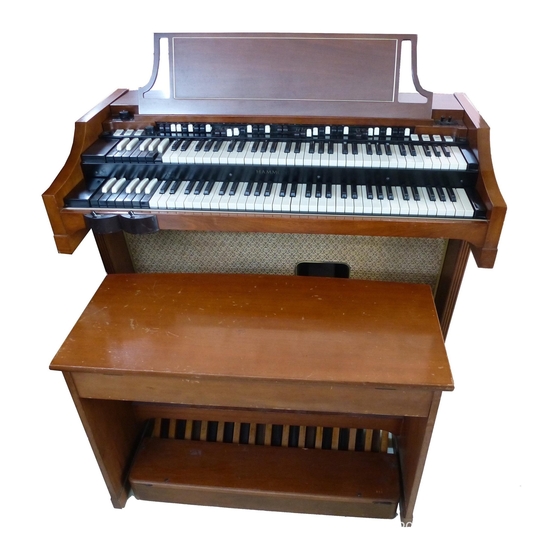
SERIES A-100
Figure 1
These Models of The Hammond Organ contain the entire tone-producing mechanism, which is
completely electrical in operation. Within it are produced all the tones and tone combinations of the
organ. The electrical waves are made audible by suitable amplifiers and loud speakers, contained
within the console. The block diagram (Figure 7) shows the chief components of the instrument.
Electrical impulses of various frequencies are produced within a unit known as the "tone generator",
containing a number of "phonic wheels" or "tone wheels" driven at predetermined speeds by a
synchronous motor and gear arrangement. Each phonic wheel is similar to a gear, with high and low
spots, or teeth, on its edge. As the wheel rotates these teeth pass near a permanent magnet, and the
resulting variations in the magnetic field induce a voltage in a coil wound on the magnet. This small
voltage, when suitably filtered, produces one note of the musical scale, its pitch or frequency depending
on the number of teeth passing the magnet each second.
A note of the organ, played on either manual or the pedal keyboard, generally consists of a fundamental
pitch and a number of harmonics, or multiples of the fundamental frequency. The fundamental and eight
harmonics available on each playing key are individually controllable by means of drawbars and preset
keys. By suitable adjustment of these controls the player is enabled to vary the tone colors at will.
The resulting signal passes through the expression or volume control and through the preamplifier
(where vibrato is introduced) to the power amplifier and the self-contained speakers.
Reverberation is added electrically by a second amplifier which drives a reverberation speaker, also
located in the console
1
tuttotastiere.com
Advertisement
Table of Contents

Subscribe to Our Youtube Channel
Related Manuals for Hammond Organ A-100 Series


Summary of Contents for Hammond Organ A-100 Series
- Page 1 SERIES A-100 Figure 1 These Models of The Hammond Organ contain the entire tone-producing mechanism, which is completely electrical in operation. Within it are produced all the tones and tone combinations of the organ. The electrical waves are made audible by suitable amplifiers and loud speakers, contained within the console.
-
Page 2: Preset Keys
DESCRIPTION Each Hammond Organ console (Fig. 1) includes two manuals or keyboards: the lower, or Great, and the upper, or Swell; and a pedal keyboard of 25 keys. The operation of the controls of this model is covered in the following paragraphs. -
Page 3: Harmonic Drawbars
HARMONIC DRAWBARS Each console has four sets of harmonic drawbars, two for each manual. Figure 4 shows one group of harmonic drawbars, by which the organist is enabled to mix the fundamental and any, or all, of eight different harmonics in various proportions. The third bar from the left controls the fundamental, and each of the other bars is associated with a separate harmonic. - Page 4 VIBRATO The vibrato effect is created by a periodic raising and lowering of pitch, and thus is fundamentally different from a tremolo, or loudness variation. It is comparable to the effect produced when a violinist moves his finger back and forth on a string while playing, varying frequency...
-
Page 5: Tone Generator
TONE GENERATOR The main tone generator furnishes 91 different musical frequencies. It includes a tone wheel, magnet, and coil for each frequency. Mounted on top of the generator are tuned filters to insure purity of the tones. PREAMPLIFIER The Preamplifier is located within the console, suspended from the main generator shelf. Its purpose is to amplify the signals before sending them to the amplifier. -
Page 6: Installation And Maintenance
INSTALLATION AND MAINTENANCE The organ must be connected to a regulated-frequency source of the voltage and frequency specified on the name plate. If the frequency is not regulated, the pitch of the organ will be irregular. When a console is set up for operation, the anchoring must be loosened so that the generator will float freely on its spring suspension system. -
Page 7: Technical Section
TECHNICAL SECTION THE HAMMOND TONE GENERATOR The A-100, A-101 and A-102 embodies the Hammond electro-mechanical tone generator as its source of tone. A picture of this generator is shown below. The generator assembly includes a shaded-pole induction motor for starting, a non-self-starting synchronous motor for driving the unit after it is started, and a Vibrato Scanner mounted on the synchronous motor. - Page 8 THE TONE WHEELS The main generator is a long structure in which are mounted 48 rotating assemblies, each consisting of a shaft and two discs known as tone or phonic wheels. These assemblies are coupled resiliently to the drive shaft. Each of the driving gears engages two bakelite gears associated with rotating assemblies on opposite sides (See Figure 11).
- Page 9 The two spring couplings on the motor shaft, the flexible couplings between sections of the drive shaft, and the tone wheel spring couplings all contribute to absorbing variations in motor speed. The synchronous motor does not deliver absolutely steady power, but rather operates with a series of pulsations, one with each half cycle.
-
Page 10: Generator Filters
The tip of each magnet, as well as the edge of each tone wheel, is coated with lacquer to prevent corrosion, for, should oxidation set in, the change in tooth shape would introduce irregular frequencies. Locations of the various magnet and coil assemblies are shown in Figure 12. They are identified by their frequency numbers, and the broken line between any two numbers indicates that these two frequencies are supplied by one tone wheel assembly. - Page 11 These transformers and condensers are mounted on the top of the generator assembly. The transformers are mounted at an angle, thus minimizing interference between them. The cores of the transformers are made of a special iron, and the number of laminations used is adjusted to secure the proper inductance.Wires from the magnet coils connect to the transformers, and wires from the transformers lead to the terminal strip on the generator.
- Page 12 THE MANUAL CHASSIS ASSEMBLY The manual chassis assembly, Fig. 14, includes the upper and lower manuals and the preset panel. It has a terminal strip under each manual to accommodate the necessary frequency wires from the tone generator assembly. Each manual has 61 playing keys, 9 preset keys, and 2 adjust keys, each of which operates nine small bronze contact springs with precious metal points (See Figure 15).
- Page 13 ARRANGEMENT OF MANUAL CONTACTS When a playing key is pressed, its nine frequencies are impressed on the nine busbars of the manual. As there are no wires connected to these busbars, a preset or adjust key must be depressed before any circuit can be completed.
- Page 14 Manual Busbar Shifters The precious metal contact surfaces of the key contacts and busbars are not subject to corrosion, and the manuals are sealed to exclude dust as far as possible. In spite of these precautions an occational particle of dust may lodge on a contact and cause the note to be scratchy, noisy, or silent, and for this reason a busbar shifting mechanism is provided on each manual to slide the busbars endwise and thus provide a fresh contact surface.
- Page 15 Manual Wiring Figure 19, a wiring chart for the playing manuals, will be helpful in tracing difficulties associated with the generator or manuals. Both manuals are wired alike. Preset Panel The tone signals from the preset keys are carried by color-coded wires to the divided preset panel in the back of the console.
- Page 16 Once a key has been depressed, the soft spring remains under the tube. It is backed by the short stiff spring to give it sufficient tension to hold the key down. When the next preset key is depressed, the cradle is forced down and outward, permitting the previously operated key to come up, but again locking the one last depressed.
- Page 17 Key Number Note Drawbar 1 Drawbar 2 Drawbar 3 Drawbar 4 Drawbar 5 Drawbar 6 Drawbar 7 Drawbar 8 Drawbar 9 Frequency Number Figure 19 tuttotastiere.com...
- Page 18 PEDAL SWITCH ASSEMBLY The pedal switch (shown in Figure 20) is similar in internal construction to the manuals except that only four busbars are included instead of nine (Figure 21). Each of the 25 pedals actuates a double set of contact springs, making eight contacts available for each note.
- Page 19 Figure 23 is a wiring chart for the pedals,showing the frequency numbers appearing on each pedal contact. 2nd Harm 10th 12th Pedal #. Note Fund 4th Harm 6th Harm 8th Harm /3rd Harm Harm Harm Harm Frequency Number Frequencies used in pedal switch (Figure 23) tuttotastiere.com...
- Page 20 Pedal Switch Busbar Shifters The pedal switch is equipped with busbar shifters similar to those on the manuals. The pedal busbar shifter is a Slotted stud on the near surface of the pedal switch, near the left end as you look in at the back. It should be adjusted as described under "Manual Busbar Shifters"...
-
Page 21: Principle Of Operation
Fig.25 The Hammond Organ vibrato equipment (see simplified block diagram, ) varies the frequency of all tones by continuously shifting their phase. It includes a phase shift network or electrical time delay line, composed of a number of low pass filter sections, and a capacity type pickup or scanner, which is motor driven so that it scans back and forth along the line. - Page 22 Figure 27 shows the construction of the vibrato switch. The scanner (Fig. 28) is mounted on the main generator synchronous motor and driven at 412 revolutions per minute. It is a multi-pole variable condenser with 16 sets of stationary plates and a rotor whose plates mesh with the stationary ones. In figure 28B two sets of plates have been removed to show the rotor.
-
Page 23: Theory Of Operation
The complete shows the vibrato circuit. schematic 1. THEORY OF OPERATION The percussion tones are produced by borrowing the 2nd or 3rd harmonic signal from the corresponding drawbar (of the upper manual "B " adjust key drawbar group), amplifying it, returning part of it to the same drawbar, and conducting the balance through push-pull control tubes, which when keyed cause the signal to fade away at a pre-determined rate. - Page 24 3. FOUR PERCUSSION CONTROL TABLETS, CUTOFF CONTROL, AND THEIR FUNCTIONS. The Percussion On-Off Tablet when turned "on" does five things to the signals of the upper manual "B" adjust key drawbars. (a) It disconnects the 2nd harmonic drawbar from its signal wire. (b) It disconnects the 3rd harmonic drawbar from its signal wire.
-
Page 25: Phono Input
SCHEMATICS Schematic #1 - Figure 30 - Hammond Organ models A-100, A-101, A-102 schematic. - Figure 31 - Hammond Organ models A-100, A-101, A-102 wiring diagram. Schematic #2 Schematic #3 - Figure 32 - AO-39 Power Amplifier schematic.
Need help?
Do you have a question about the A-100 Series and is the answer not in the manual?
Questions and answers