Table of Contents
Advertisement
Quick Links
Advertisement
Table of Contents

Related Manuals for H-TEC Education D201

Summary of Contents for H-TEC Education D201
- Page 1 Operating Instructions D201 - Exhibition Kit...
-
Page 2: Table Of Contents
Table of contents The Exhibition Set About these instructions Safety information Contents Overview Starting up Operation Technical Data Troubleshooting Shutting Down Maintenance Transportation & Storage Disposal www.myhtec.com... -
Page 3: The Exhibition Set
These operating instructions document all process steps required for starting up and operating the Exhibition Set. We hope you enjoy many instructive hours with the Exhibition Set. The team at, H-TEC EDUCATION About these instructions • These operating instructions are intended for the supervisor in charge. -
Page 4: Contents
Contents 1x Demonstration model 2x Overflow tanks 1x Fuel cell gas flow indicator / Water trap 1x Solar module 1x Fan module www.myhtec.com... - Page 5 2x Cable Set Connection cables, 4mm, 50cm length, red Connection cables, 4mm, 50cm length, black 1x Companion text book Additional tools required: 2.5mm hex key www.myhtec.com...
-
Page 6: Overview
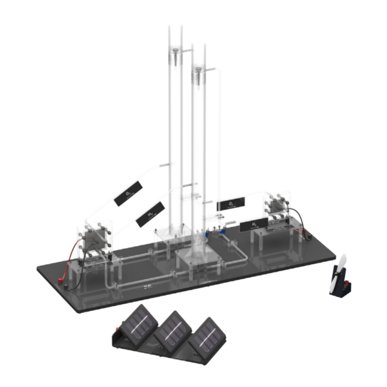
Overview The “Exhibition” demonstration model at a glance The “Exhibition” demonstration model consists of an electrolyser, two water reservoirs and a fuel cell, all mounted to a black base plate. When the electrolyser is supplied with electrical energy, it produces hydrogen and oxygen from distilled water. The gases enter the fuel cell via the water reservoir and a system of tubes where, provided a load (consumer) is connected, they are converted back to water while electrical energy and heat are being generated. -
Page 7: Starting Up
Starting up Fig. 2: Assembly Assemble the demonstration model as shown in Figure 2. Remove both locking screws by turning them counter-clockwise. Place Gas Flow indicator below fuel cell, and attach tubes from fuel cell. The preparation for storage and transportation is carried out in reverse order to assembly. Do not yet connect the power supply to the electrolyzer. -
Page 8: Operation
Operation Fig. 4: Exhibition Set operation Read and observe the general safety instructions. Using the connecting cables, connect the propeller (A) with the respective connections (B) on the fuel cell, while ensuring correct polarity (red = “+”, black = “-”). Using the connecting cables, connect the solar module (C) with the respective connections (D) on the electrolyzer, while ensuring correct polarity (red = “+”, black = “-”). - Page 9 During operation, small amounts of water pass through the electrolyzer’s polymer electrolyte membrane (PEM) from the oxygen side. This may cause the water level to rise on the hydrogen side and fall on the oxygen side. In addition, distilled water is being consumed during operation.
- Page 10 CAUTION Risk of damage due to electrical overload Any operation beyond the electrical specifications will lead to irreparable damage to the electrolyzer. Never operate the electrolyzer beyond the electrical specifications stated in the technical data. CAUTION Risk of damage due to voltage Applying voltage to a fuel cell or a solar module leads to irreparable damage to the components.
-
Page 11: Technical Data
Technical data Exhibition model: H x W x D: 700 x 300 x 1300 mm Weight: 4.8 kg Electrolyzer: Production: 35 mL/min Production: 17.5 mL/min Permissible current: 0 - 5 A Permissible operating voltage: 0 - 2.0 VDC Electrode area: 36 cm Guide value for distilled water: <2 μS/cm... -
Page 12: Troubleshooting
Troubleshooting Despite hydrogen and oxygen being produced, the load connected to the fuel cell is not working. Possible Cause: The overflow tanks are not secured firmly in place. Solution: Turn the overflow tanks clockwise, until they are secured firmly in place. Possible Cause: The load has not been connected correctly, or is not receiving any voltage. - Page 13 The fan does not work despite a supply voltage being present and the connecting cables being connected correctly. Possible Cause: The fan is broken. Solution: Contact H-TEC Education The output of the solar module is insufficient, despite adequate light intensity and the connecting cables being connected correctly. Possible Cause: The solar module is defective.
-
Page 14: Shutting Down
Shutting down After disconnecting the power supply from the electrolyser, continue operating the fuel cell until the connected load stops by itself. This allows some water to remain in the fuel cell, moistening the PEM. In addition, this procedure also prevents that hydrogen is released unnecessarily. CAUTION Risk of injury from hydrogen ignition! Escaping hydrogen may ignite when in proximity to an ignition source. -
Page 15: Maintenance
Maintenance The components of this product do not require maintenance. The following points should be observed, however: Use fresh, distilled water (σ < 2 μS/cm) for each new start-up. After operation, remove the water from the water reservoir. Transportation and storage With regard to transport and storage of the product, the following points should be observed to ensure a long service life. - Page 16 © H-Tec Education, 2019. No part of this guide may be reproduced in whole or in part in any manner without the express written permission of H-Tec Education. Subject to technical changes. H-TEC EDUCATION 1902 Pinon Dr. Unit B College Station, TX 77845...
Need help?
Do you have a question about the D201 and is the answer not in the manual?
Questions and answers