Table of Contents
Advertisement
Available languages
Available languages
Quick Links
Advertisement
Chapters
Table of Contents

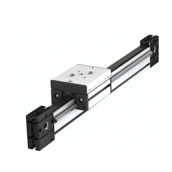
Summary of Contents for ITEM LRE 8 D14 ZU 40 R25
- Page 1 Lineareinheit LRE 8 D14 ZU 40 R25 Anwendungs- und Montagehinweise...
-
Page 2: Table Of Contents
Inhalt Symbole, Sicherheit Einlegen des Zahnriemens Allgemeiner Gefahrenhinweis Befestigungsmöglichkeiten Bestimmungsgemäße Verwendung Befestigung und Spannen des Zahnriemens R25 T10 Nicht bestimmungsgemäße Verwendung Positionierung von Endschaltern Betriebsparameter Positionierung von Endschalternocken Vorbereitung Anschluss des Antriebssatzes 8 40 D40/D15 - 0.0.668.02 Montage Anschluss des Antriebssatzes 8 D40/D15 AP/WP 60 - 0.0.672.73 13 Schlitten LRF 8 D14 160x160/200x160 Schlittenanschlag LRE 8 Anwendungsmöglichkeiten... -
Page 3: Bestimmungsgemäße Verwendung
Verhindern Sie die Möglichkeit des Einschließens von Personen im begehbaren Gefahrenbereich der Anlage. Bestimmungsgemäße Verwendung Die Lineareinheit LRE 8 D14 ZU 40 R25 mit Steuerung und Motor ist im Sinne ▪Sie fachlich ausgebildet sind, der Maschinenrichtlinie 2006/42/EG eine unvollständige Maschine. Diese darf ▪Sie von Ihrem Unternehmen hierzu autorisiert sind,... -
Page 4: Betriebsparameter
Betriebsparameter Die Lineareinheit LRE 8 D14 ZU 40 R25 wird generell aus Baugruppen und auf Maß zugesägten Profilen der Baureihe 8 gefertigt und ist vor der eigentlichen Montage auf Vollständigkeit zu überprüfen. Das maximal mögliche Antriebsmoment beträgt: M = 20 Nm Das Reibmoment oder Anfahrmoment ohne Last der Lineareinheit in Abhängig-... -
Page 5: Vorbereitung
Lineareinheit LRE 8 D14 120x80 ZU 40 R25 Maximaler Hub H 5760 mm Sicherheitsabstand S Grundmasse (bei Hublänge 0 mm) m 10,3 Masse pro mm Hub m 14,2 g/mm Gesamtmasse m = + H * m Wiederholgenauigkeit 0,15 Maximale Beschleunigung Maximale Verfahrgeschwindigkeit Vorschubkonstante mm/U... -
Page 6: Montage
Montage Wellenklemmprofil und Welle: ▪Eindrücken eines Wellenklemmprofils in die entsprechende Nut des Träger- profils Der Zusammenbau von Trägerprofil, Wellenklemmprofil und Welle kann nach verschiedenen Methoden vorgenommen werden. ▪Eindrücken der Welle mit Hilfe eines Schraubstockes (Schutzbacken verwenden) Zur Erleichterung der Montage sollten die Außenflächen des Wellenklemmpro- fils, die Kontakt mit dem Trägerprofil haben, vor dem Eindrücken in die Nut mit ▪Zweite Seite in gleicher Reihenfolge einem Öl- oder Fettfilm versehen werden. - Page 7 Der so vormontierte Führungswagen wird auf das mit den Führungswellen heit geprüft und nachjustiert. Anschließend wird die Position der Doppellage- vorbereitete Trägerprofil aufgeschoben. reinheit mit zwei Halbrundschrauben M8 von unten gesichert. Anschließend werden die seitlichen Gewindestifte abwechselnd in kleinen Zum Schluss werden die Abstreif- und Schmiersysteme sowie Abdeckkappen Schritten angezogen, bis der Schlitten spielfrei an den Führungswellen anliegt.
-
Page 8: Anwendungsmöglichkeiten
Anwendungsmöglichkeiten In Kombination mit dem Trägerprofil 8 80x40 und dem Schlitten LRF 8 D14 160x160: 12 h9 70.4 Ø14 In Kombination mit dem Trägerprofil 8 80x80 und dem Schlitten LRF 8 D14 200x160: 110.4 12 h9 Ø14 In Kombination mit dem Trägerprofil 8 120x80 und dem Schlitten LRF 8 D14 200x160: ∅12 h9 110.4 Ø14... -
Page 9: Zahnriemenumlenkung 8 40 R25 Mit Bohrung
Zahnriemenumlenkung 8 40 R25 mit Bohrung Ist der Schlitten auf dem Trägerprofil montiert und spielfrei justiert werden die des Zahnriemens R25 T10 zum Aufbau von Lineareinheiten in Verbindung mit Zahnriemenumlenkungen vorbereitet. Die Zahnriemenumlenkungen 8 40 R25 den Führungen, Getrieben und Antriebseinheiten. mit Bohrung für Spreiznabenkupplung dienen dem Antrieb bzw. -
Page 10: Befestigungsmöglichkeiten
Befestigungsmöglichkeiten Anschließend werden die Zahnriemenumlenkungen am Trägerprofil befestigt. Anbindung der Zahnriemenumlenkung 8 40 R25 an Profile der Baureihe 8 (Bauhöhe 80 mm und größer). Trennen des Spezial-Nutensteins an der Sollbruchstelle. Befestigungslage der Zahnriemenumlenkung 8 40 R25 an unterschiedlichen Profilen je nach Lage des rückgeführten Zahnriemens. Befestigung und Spannen des Zahnriemens R25 T10 Zum Befestigen und Spannen des Zahnriemens an einem Führungsschlitten sowie ein Zahnriemenspanne Gegenlager 8R25 in der entsprechenden... -
Page 11: Positionierung Von Endschaltern
Falls die LRE 8 D14 ZU40 R25 komplett vormontiert geliefert wird, muss die Vorspannung entsprechend den Bestellvorgaben geprüft werden. Nach einer Einlaufzeit von 24h wird die Betriebsspannung des Zahnriemens erneut geprüft und bei Bedarf nachgespannt. Beim Spannen wird zunächst der Nullpunkt ermittelt an dem der ungespannte Zahnriemen vollständig ohne Durchhang anliegt und die Vorspannung beginnt. -
Page 12: Positionierung Von Endschalternocken
Anschluss des Antriebssatzes 8 40 D40/D15 – 0.0.668.02 Der Antriebssatz 8 40 D40/D15 dient zum Anschluss beliebiger Antriebe an Die vorbereitete Kupplung passt auf die Antriebswelle und überträgt das die Lineareinheit LRE 8 D14 ZU 40 R25. Antriebsmoment spielfrei. [mm] 8 40 D40/D15 ⌀... -
Page 13: Anschluss Des Antriebssatzes 8 D40/D15 Ap/Wp 60 - 0.0.672.73
Der Antriebssatz 8 D15/D40 AP/WP 60 – 0.0.672.73 dient ausschließlich Die Kraftübertragung der Kupplung zur Antriebswelle erfolgt reibschlüssig. zum Anschluss der item Antriebe an die Lineareinheit LRE 8 D14 ZU 40 R25. Zur reibschlüssigen Verbindung der Antriebswelle muss die Bohrung der Der gesamte Antriebssatz ist zur Montage auf die entsprechende Linearein- Kupplungsnabe und die Welle entfettet und gereinigt werden. -
Page 14: Schlittenanschlag Lre 8
Schlittenanschlag LRE 8 Der robuste Anschlag aus Aluminium, Schlittenanschlag LRE 8, bewahrt den Hinweis: Die meisten item Lineareinheiten vom Typ LRE werden bei der Schlitten einer Lineareinheit davor, über den berechneten oder gewünschten Konfiguration über den item MotionDesigner automatisch mit einem Schlitten- ®... - Page 15 Lineareinheit LRE 8 D14 120x80 ZU 40 R25 L=2 x S+H+320 L = Gesamtlänge in Abhängigkeit von Hub H S = Sicherheitsabstand Zur Berechnung der Positionen der Schlittenendanschläge in Abhängigkeit vom Zum Abschluss den Schlittenanschlag an den Grundkörper mit zwei Schrau- Hub können die Zeichnungen und Formeln verwendet werden.
-
Page 16: Synchronisation Lre 8 D14 Zu40 R25
Synchronisationssätze kommen zum Einsatz, wenn zwei Lineareinheiten par- Die Kupplungen sind bereits für die Aufnahme einer Synchronwelle vorbereitet. allel betrieben werden sollen. item Synchronisationssätze bestehen aus Kupp- Spreiznabenkupplungen zeichnen sich neben ihrer kompakten Bauweise durch lungen, die zwischen zwei Lineareinheiten montiert und mit einer Synchronwel- einfache Handhabung aus. -
Page 17: Schmierung
Empfohlener Nachölzyklus: alle 6 Monate oder alle 2500 km. Die Filze sind im Ideale Betriebsbedingungen: Auslieferungszustand bereits mit Öl getränkt. Umgebungstemperatur: 10°C ... 40°C Synthetisches Schmieröl ISO VG 460 z.B. item Laufbahn-Öl für Linearführungen Belastung: < 5% Artikel-Nr.: 0.0.612.75 Pro Wartungsintervall ist die folgende Menge in jede Wartungsbohrung einzu-... - Page 18 Industrietechnik GmbH Friedenstraße 107-109 42699 Solingen Deutschland Den Anwendungs- und Montagehinweis Telefon +49 212 6580 0 finden Sie im Internet im Downloadbereich Telefax +49 212 6580 310 des Produktes. info@item24.com item24.com...
- Page 19 Linear Unit LRE 8 D14 ZU 40 R25 Notes on Use and Installation...
- Page 20 Linear Unit protection that apply in the country and place of work where the product is LRE 8 D14 ZU 40 R25. The text below usually refers to these as the Linear Unit being used.
-
Page 21: Correct Use
Correct use Linear Unit LRE 8 D14 ZU 40 R25 with Controller and Motor is a partly completed ▪You are appropriately qualified, machine as defined in the Machinery Directive (2006/42/EC). It must only be ▪You are authorised to do so by your company,... -
Page 22: Operating Parameters
Operating parameters Linear Unit LRE 8 D14 ZU 40 R25 is generally constructed from Line 8 profiles that have been cut to size and various assemblies. Before starting installation work, it is important to check that all parts are present. -
Page 23: Preparation
Consult the manufacturer if using in very salty air. Deflection in the linear axis The area should be free from mould and fungus and show no traces of rodents of LRE 8 D14 ZU 40 R25 should not exceed 1 mm over an axis of 1000 mm. In or other pests. -
Page 24: Installation
Installation Shaft-Clamp Profile and Shaft: ▪Press the Shaft-Clamp Profile into the relevant groove of the support profile There are various methods for assembling support profile, Shaft-Clamp Profile ▪Use a vice (fitted with protective jaw plates) to press in the Shaft and Shaft. - Page 25 Slot the guide carriage in its preassembled state onto the support profile that unit is free from play by pushing it along the entire length of the guiding Shafts you fitted the guiding Shafts to earlier. and make any adjustments that are necessary. Next, secure the position of the Double-Bearing Unit from below using two Button-Head Screws M8.
- Page 26 Application options In combination with Profile 8 80x40 as a support profile and Slide LRF 8 D14 160x160: 12 h9 70.4 Ø14 In combination with Profile 8 80x80 as a support profile and Slide LRF 8 D14 200x160: 110.4 12 h9 Ø14 In combination with Profile 8 120x80 as a support profile and Slide LRF 8 D14 200x160: ∅12 h9...
-
Page 27: Timing-Belt Reverse Unit 8 40 R25 With Bore
Timing-Belt Reverse Unit 8 40 R25 with Bore Once the carriage has been fitted to the support profile and adjusted to elimi- or reverse Timing Belt R25 T10 to build Linear Units combined with guides, nate play, the Timing-Belt Reverse Units can be prepared. Timing-Belt Reverse Gearboxes and Drive Units. -
Page 28: Securing And Tensioning Timing Belt R25 T10
Attachment options Next, fasten the Timing-Belt Reverse Units to the support profile and align the Connecting Timing Belt Reverse Unit 8 40 R25 to Line 8 profiles Timing Belt with the profile. (construction height 80 mm and over). Separating the special T-Slot Nut at the pre-determined breaking point. Fastening arrangement of Timing Belt Reverse Unit 8 40 R25 on different profiles depending on the position of the Timing Belt when fed back through. -
Page 29: Positioning Proximity Switches
If the LRE 8 D14 ZU 40 R25 has been supplied fully preassembled, you will need to check the pre-tensioning against the order specifications. After a running-in time of 24 hrs, check the operating tension of the Timing Belt again and adjust it if necessary. -
Page 30: Positioning Proximity-Switch Cams
Positioning Proximity-Switch Cams The Proximity-Switch Cams are used to mark the electric terminal position limit and the reference point of the moving unit and Timing Belt. Push them into the Timing belt from the smooth side, locating them at the desired point along the length of the belt and centrally in the width of the belt. -
Page 31: Connecting Drive Set 8 D40/D15 Ap/Wp 60 - 0.0.672.73
Force is transferred from the Coupling to the drive shaft by means of frictional drives to Linear Unit LRE 8 D14 ZU 40 R25. The Drive Set is fully prepared for resistance. The Shaft and the hole in the coupling hub must be degreased and installation on the corresponding Linear Unit. -
Page 32: Slide Stop Lre 8
Units from item are automatically fitted with a Slide Stop that can be moved for the system. Thanks to its special shape, the Slide Stop can be used with to a different position or removed entirely, as required. - Page 33 Linear Unit LRE 8 D14 120x80 ZU 40 R25 L=2 x S+H+320 L = Gesamtlänge in Abhängigkeit von Hub H S = Sicherheitsabstand The drawings and formulae can be used to help calculate the relevant end Finally, use two M6 screws to attach the Slide Stop to the basic unit and tighten positions when installing the Slide Stops in relation to travel.
-
Page 34: Synchronising Lre 8 D14 Zu 40 R25
Coupling. How long a Synchroniser Shaft can be depends Synchronising Sets from item can be used to operate two Linear Units in parallel on its operating speed. To determine the maximum length for a given speed with just one motor. -
Page 35: Lubrication
Recommended re-oiling period: Every 6 months or every 2500 km. The felt Ideal operating conditions: pieces are supplied in ready-oiled condition. Ambient temperature: 10°C ... 40°C Synthetic lubrication oil ISO VG 460, e.g. item Track Oil for Linear Guides Load: < 5% (0.0.612.75). - Page 36 Industrietechnik GmbH Friedenstrasse 107-109 42699 Solingen, Germany Germany You can find the Notes on Use and Instal- Telephone +49 212 6580 0 lation online, in the download section for Fax +49 212 6580 310 this product. info@item24.com item24.com...
Need help?
Do you have a question about the LRE 8 D14 ZU 40 R25 and is the answer not in the manual?
Questions and answers