Table of Contents
Troubleshooting

Related Manuals for Neutronics 3100

Summary of Contents for Neutronics 3100
- Page 1 Instruction manual Model 3100 Oxygen analyzer / controller Trace to percent O2 measurement 0.1 PPM to 100% range Manual file name: MN-A-0005 Revision Level: C Manual Part Number: C5-06-4900-16-0 Revision date: December 22, 2016...
-
Page 2: Table Of Contents
System installation and start-up ......................8 Installing the analyzer ........................8 2.1.1 Step 1 – Locate the Model 3100 analyzer ................8 Page ii Manual file name: MN-A-0005, Rev. C Manual P/N: C5-06-4900-16-0... - Page 3 Instruction Manual Model 3100 Analyzer 2.1.2 Step 2 – Install the remote sensor module (RSM) ..............9 2.1.3 Step 3 – Install the analyzer ..................... 9 Step 3 – Start up and commissioning .................... 13 ...
-
Page 4: Welcome
Neutronics, Inc. This work is protected under Title 17 of the US Code and is the sole property of Neutronics Inc. No part of this document may be copied or otherwise reproduced, or stored in any electronic information retrieval system, except as specifically permitted under US copyright law, without the prior written consent of Neutronics Inc. -
Page 5: Safety Instructions
Do not expose the Model 3100 to flame or high temperatures. Do not expose the Model 3100 to flammable gases or vapors. The unit is not rated explosion proof or intrinsically safe. Ensure that the pressure of gas entering the remote sensor module (RSM) is compatible with the operating instruction. -
Page 7: Introduction
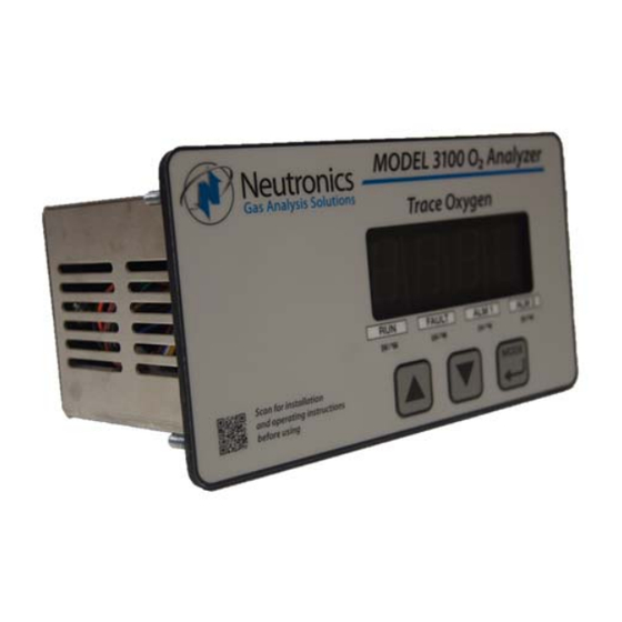
The Neutronics Model 3100 Compact Series analyzer is a microprocessor-based instrument for oxygen measurement and process control applications. The Model 3100 analyzer is designed for use with a separate Neutronics Remote Sensor Module (see Figure 1). The RSM features the Neutronics ZR100 rapid–response zirconium oxide (ZrO2) oxygen sensor, a ceramic, solid-state device with an extremely fast response to oxygen, a wide measurement range, and a robust design. -
Page 8: System Hardware Overview
Main board The main board (see Figure 2) houses the microprocessor and supporting electronics for controlling the operation of the Model 3100 Analyzer. The main board receives the sensor input and provides the control and display functions of the analyzer. -
Page 9: Chassis
Instruction Manual Model 3100 Analyzer Fig. 3, Control panel 1.3.6 Chassis The stainless steel chassis or electronics enclosure (see Figure 4) is designed to provide a general level of protection against mechanical damage from the local environment. It is an important part of the electrostatic discharge (ESD) shielding design. -
Page 10: Sensor
The sensor determines the oxygen concentration of the gas in real time. The RSM is an integral part of the Model 3100 analyzer system (see Figure 6). It is available in two (2) configurations: pump-driven and positive pressure-driven. Refer to the Remote Sensor Module instruction manual for more details. -
Page 11: Analyzer Inputs And Outputs
Fault relay output The Fault relay output is used to indicate that there is at least one system fault active on the Model 3100 analyzer (see section 4.3.1). The relay output activation is non fail-safe, and is not configurable. The Fault relay contacts are Form B (SPST), voltage-free. -
Page 12: Heater Ok Output
1.4.5 Heater OK output The Heater OK output relay is a system diagnostic used to indicate that the Model 3100 has detected a sensor heater temperature that is not within specification tolerance (see section 4.3.1 – Fault Codes and Definitions). The relay output activation is non fail-safe, and is not configurable. The Heater OK relay contacts are Form B (SPST), voltage-free. -
Page 13: Control Panel User Interface
RUN indicator LED The purpose of the RUN indicator LED is to inform the user via the control panel that the Model 3100 is measuring the concentration of the sample gas and updating the display and outputs accordingly (with no alarm or fault conditions present). -
Page 14: System Installation And Start-Up
2.1 Installing the analyzer 2.1.1 Step 1 – Locate the Model 3100 analyzer Select a suitable location for mounting the analyzer where the digital display and status LED’s will be easy to read and the interface buttons on the display panel will be easy to access Cut/drill the mounting panel to the specifications shown in Figure 8 Clearance holes for the #8-32 threaded mounting studs do not need to be tapped. -
Page 15: Step 2 - Install The Remote Sensor Module (Rsm)
Model 3100 analyzer will be installed. CAUTION: The model 3100 housing is not rated waterproof. Do not mount the analyzer or the sensor in an area where it may contact water or other liquid elements. - Page 16 Model 3100 Analyzer Instruction Manual Fig. 9, Label on top of analyzer chassis 2.1.3.1 Remote sensor module input All connections to the Remote Sensor Module (RSM) are made by connecting the supplied interface cable between the analyzer and the RSM. Plug the cable connectors into the mating receptacles on the analyzer chassis and RSM.
- Page 17 TB3 on the rear of the analyzer chassis. The analog current output is a negative ground, non-isolated 0- 20mA, or 4-20 mA current loop. 12 VDC power is supplied internally by the Model 3100 analyzer. Maximum electrical loading is 250 Ohms. Connect the terminal pins in accordance with the schematic shown on the terminal ID label on the top of the analyzer chassis.
- Page 18 Model 3100 Analyzer Instruction Manual Use 20-AWG, 2-conductor, stranded-wire, twisted pairs for the connections. It is not necessary to use shielded cable for the Analog current output, with or without electrical barriers. If shielded cable is used, it should be drained to dc ground at the auxiliary equipment.
-
Page 19: Step 3 - Start Up And Commissioning
2.2.1 Power up check list The Model 3100 is shipped ready to use. Factory default configuration settings are listed in Appendix C. Review the factory default configuration settings before commissioning your system. If you choose to change any of the factory default settings, refer to sections 4.1.1 and 4.1.2. -
Page 20: Step 2 -- Calibrate The Unit
Refer to section 3.2.3 for information about setting the alarm- 2 level. The Model 3100 should now be ready for commissioning. Neutronics Inc. offers commissioning and Factory Acceptance Testing services by our certified technicians. You may contact the Neutronics factory toll-free at (800) 378-2287 or (610) 524-8800. -
Page 21: Operation
“MODE” key. When a user mode is accessed via the control panel, the Model 3100 aborts any system mode active and holds the state of Alarm-1 and Alarm-2 outputs until the user returns the unit to “RUN” mode. -
Page 22: Calibration
4.2). Refer to section 4.2.2 for the display reading validation procedure. 3.2.1.1 Calibration – Introduction For best application-driven accuracy, the Model 3100 is capable of a two-point calibration – explained in this manual as Reference calibration, and Span calibration. Reference calibration is always performed using ambient air with an oxygen concentration of 20.9%. -
Page 23: Set/View Alarm-1 Mode
Instruction Manual Model 3100 Analyzer 3.2.1.5 Step 4 – Calibrate the analyzer with reference gas After applying a regulated stream of calibration gas to the sensor, press and release the “MODE” key once. The 7-segment alphanumeric display will show “CAL”, then an oxygen concentration value. Adjust the displayed oxygen concentration value to read 20.9% oxygen by pressing the “UP”... -
Page 24: Return To Run Mode
Values are compared against monitored inputs and other monitored system hardware in real time. 3.3.1 Self-test & warm-up mode When the Model 3100 is started up, it enters into Self-Test & Warm-up mode automatically, followed by a sensor heater warm-up period (see section 2.2.1). When the sensor heater reaches operating temperature, the analyzer aborts the warm-up routine, checks the current sensor signal, updates the 7- segment LED display, status LED’s, and Analog outputs, then enters into the appropriate system mode... -
Page 25: Alarm-1 Active Mode
3.3.5 FAULT Active mode The Model 3100 initiates Fault Active mode when it has detected that one or more Fault conditions have been satisfied (see section 4.3.1). The “FAULT” indicator LED will turn on and the Fault relays will change state. -
Page 26: Setup, Maintenance, And Troubleshooting
System setup via control panel keypad The control panel User Setup menu may be accessed from the Model 3100 control panel by pressing and holding the “MODE” key for at least 6-seconds -- until the 7-segment alphanumeric display shows “---.“... - Page 27 4.1.1.1 User Setup Mode A: Display range select Setup Mode A allows the user to map the display and electrical output range scale of the Model 3100 to suit the application (see Appendix E – Range / Output Chart). Valid settings are listed in Figure 15.
- Page 28 Setup Mode 7 is the zero calibration range that is set by the factory (see Figure 20). It should not be adjusted by the user. If the user changes the zero calibration range, the Model 3100 will not operate properly.
- Page 29 Instruction Manual Model 3100 Analyzer 4.1.1.8 User Setup B: RS-232 baud rate Setup Mode B allows the user to set the RS-232 communications baud rate. Valid settings are listed in Figure 22. Fig. 22, Valid settings for setup Mode F 4.1.1.9 User Setup C: Clean mode enable...
-
Page 30: System Setup Via Rs-232 Service Port
Turn off your computer and remove power from the Model 3100. Complete the instructions for wiring and connecting the Model 3100 to a PC computer (see section 2.1.3.10). Apply power to the Model 3100 and then start up the PC computer. - Page 31 If the typed letters DO show on the monitor screen and serial communications with the Model 3100 still has not been established, then PC COM port pins 2 & 3 (3100 pins 9 & 10) may be reversed. Verify the cable wiring (section 2.1.3.10).
- Page 32 Helpful Hint: For viewing convenience, before requesting specific information from the Model 3100, disable automatic 1-second updates from the Model 3100 and allow access of information by-request- only (see section 4.1.2.4.1). Type “SSERFMT=0”, followed by the Return key. To return to automatic 1- second updates of data from the analyzer in Human Readable format (see section 4.1.2.4.2), type...
- Page 33 | Mode tab | O2 Concentration tab | Alarm-1 status tab | Alarm-2 status tab | list of Fault codes active tab. For detailed information on data formats, please contact the Neutronics Service Department. 4.1.2.5 Advanced Level 1 access Advanced Level-1 access is the computer-interfaced user Setup mode.
- Page 34 “F” on the RS-232 Terminal. To go back, use the <Esc> or “Q” key on the RS-232 terminal. 4.1.2.9 System information display The System Information Display U10 is a list of all the current settings for the Model 3100 analyzer. It is accessed from the Setup Main Menu by typing “1” or “I” on the RS-232 Terminal.
- Page 35 Instruction Manual Model 3100 Analyzer by typing “2” or “R” on the RS-232 Terminal. To go back, use the <Esc> or “Q” key on the RS-232 terminal. Fig. 29, Relay configuration menu 4.1.2.10.1 Alarm-1 and Alarm-2 relays fail-safe This parameter allows the user to set the Alarm-1 and Alarm-2 relays to either fail-safe or non-fail-safe action.
- Page 36 4.1.2.10.7 Fault Relay Active during Warm-up This setting determines the active status of the Fault relay during the Model 3100 warm-up routine (section 4.3.1.2). The activate setting may be set to “YES” or “NO”. This setting is accessed from the Alarm Relay Setup Menu by typing “7”...
- Page 37 Instruction Manual Model 3100 Analyzer Fig. 30, Analog output configuration menu 4.1.2.11.1 Analog voltage output range This menu sets the Analog Voltage Output full-scale value. Valid settings: 0 (0-5 VDC minimum to full scale), 1 (0-10 VDC minimum to full scale) or 2 (0-1 VDC minimum to full scale). This setting must match the RA and RB hardware jumper settings on the bottom of the main CPU PCB (section 4.1.3).
- Page 38 The RS-232 Display/Auto-Range Setup menu U14 provides access for the user to map the display and analog output range scale(s) of the Model 3100 to suit the application (see Appendix E – Range / Analog output Chart). The Analog Output Range may be set to: 1 (0-10 PPM), 2 (0-100 PPM), 3 (0-1,000 PPM), 4 (0-10,000 PPM), 5 (0-10 %), 6 (0-100 %), 8 (Auto-range).
- Page 39 Instruction Manual Model 3100 Analyzer 4.1.2.13 RS-232 serial output configuration menu (U50) This menu provides access to set the RS-232 serial communications options (see Figure 31). It is accessed from the Setup Main Menu by typing “5” or “S” on the RS-232 terminal. To go back, use the <Esc>...
-
Page 40: Change Factory Settings Via Hardware Jumpers
4.1.2.16.1 Calibration mode auto return to RUN This setting determines the minimum time that the Model 3100 allows after exiting from control panel or service port user menus, before returning the unit to on-line status. The calibration mode auto return setting is accessed from the Control panel Locks menu by typing ”T”... - Page 41 4.1.3.1.1 Remove the unit from service Make certain that all interfacing to the Model 3100 is disabled at the user device. Make sure that interrupting alarms, outputs, etc. will not interfere with normal process monitoring or control. Disconnect power from the Model 3100 unit. Disconnect the removable terminal blocks from the rear of the Model 3100 chassis.
-
Page 42: Routine Periodic Maintenance
4.2.1 Validate display to a known gas source With the Model 3100 analyzer in “RUN” mode, apply a Certified Standard Grade bottled gas to the RSM with an oxygen concentration within the analyzer’s configured range. Wait for the reading on the 7- segment LED display to stabilize. -
Page 43: Troubleshooting
The purpose of the alarm is to provide a control output to indicate that the sensor has not yet reached its operating temperature, and the model 3100 is not yet ready for in- service oxygen measurement. - Page 44 4.3.1.8 Fault Code 8 – A concentration reading is not yet available The “concentration reading is not yet available” fault is active when the model 3100 is not ready for online service. It is active during warm-up, calibration and during fault code-2 relay standby.
-
Page 45: Appendices
Instruction Manual Model 3100 Analyzer Appendices 5.1 Appendix A – Spare parts list Part number Description 5-06-4900-16-0 Instruction manual C1-11-1220-03-0 Vac fuses for power supply board – 1A, 250 VAC, Slo-Blo – for Vac units only C6-01-1000-73-0 RSM / Analyzer interface cable C1-17-0052-00-0 Replacement terminal block –... - Page 46 Model 3100 Analyzer Instruction Manual Part number Description Range ID voltage 0.1 – 9.9 PPM 3.13 VDC + 0.1VDC 10.0 – 99.9 PPM 3.75 VDC + 0.1VDC 100.0 – 999.9 PPM 4.38 VDC + 0.1VDC 1000 – 9999 PPM 5.00 VDC + 0.1VDC 1 –...
-
Page 47: Appendix C - Analyzer Factory Configuration Settings
Instruction Manual Model 3100 Analyzer 5.3 Appendix C – Analyzer factory configuration settings Alarm and relay setup information Alarm-1/Alarm-2 Relays Failsafe/Non-Failsafe Non-fail-safe Alarm-1/Alarm-2 Relay Ascending/Descending Ascending Alarm-1 Trigger Level 50 PPM Alarm-2 Trigger Level 100 PPM Display range Analog voltage range 0–10 PPM Fixed... -
Page 48: Appendix D - Control Panel Hot-Key Functions
Model 3100 Analyzer Instruction Manual 5.4 Appendix D – Control panel hot-key functions For convenience in operating and troubleshooting, the Model 1100 has four (4) control panel hot-key functions that can be performed quickly via the control panel without entering the normal Control panel or Service Port user menus. -
Page 49: Limited Warranty
NEUTRONICS, INC., except NEUTRONICS, INC. sensors which shall be free of said defects for a period of time from date of shipment as specified in the NEUTRONICS INC. technical specifications for that specific sensor.
Need help?
Do you have a question about the 3100 and is the answer not in the manual?
Questions and answers