Table of Contents
Advertisement
Quick Links
Installation Instructions
Distributed Low Voltage Power System
Risk of Fire, Electrical Shock, Cuts or other Casualty Hazards- Installation and maintenance of this product must be performed
by a qualified electrician. This product must be installed in accordance with the applicable installation code by a person
familiar with the construction and operation of
the product and hazards involved.
Before installing or performing any service, the power MUST be turned OFF at the branch circuit breaker. According to NEC
240-83(d), if the branch is used as the main switch for a fluorescent lighting circuit, the circuit breaker should be marked with
"SWD". All installations should be in compliance with the National Electric Code and all state and local codes.
Risk of Fire and Electric Shock- Make certain power is OFF before starting installation or attempting any maintenance.
Disconnect power at fuse or circuit breaker.
Risk of Burn- Disconnect power and allow fixture to cool before handling or servicing.
Risk of Personal Injury- Due to sharp edges, handle with care.
Failure to comply with these instructions may result in serious injury (including death) and property
damage.
DISCLAIMER OF LIABILITY: Cooper Lighting Solutions assumes no liability for damages or losses of any kind that may arise from the improper,
careless, or negligent installation, handling or use of this product.
IMPORTANT: Read carefully before installing product. Retain for future reference.
NOTICE: Product/component may become damaged and/or unstable if not installed properly.
Note: Specifications and dimensions subject to change without notice.
ATTENTION Receiving Department: Note actual fixture description of any shortage or noticeable damage on delivery receipt. File claim for common
carrier (LTL) directly with carrier. Claims for concealed damage must be filed within 15 days of delivery. All damaged material, complete with original
packing must be retained.
NOTICE: All new wiring must be fully verified before applying power.
NOTICE: Designed for indoor installation and use only. Dry location rated.
NOTICE: Do not mount near gas or electric heaters. Equipment should be mounted in locations and at adequate heights to prevent tampering by unauthorized personnel.
NOTICE: Do not use this equipment for other than its intended purpose.
MARKING SHALL INCLUDE EMERGENCY CIRCUITS
CAUTION: This unit has more than one power supply connection point. To reduce the risk of electric shock disconnect both the branch circuit-breakers or fuses and
emergency power supplies before servicing.
CAUTION: Sealed unit LVPM not user serviceable. Replace entire unit when necessary.
CAUTION: Service by Qualified Personnel Only. De-energize before opening.
NOTICE: This equipment has not been evaluated for compliance with Article 700 of the National Electrical Code, ANSI/NFPA 70.
NOTICE: Designed for indoor installation and use only. Dry location rated.
IMPORTANT SAFEGUARDS
When using electrical equipment, basic safety precautions should always be followed including the following:
a) READ AND FOLLOW ALL SAFETY INSTRUCTIONS.
b) Do not use outdoors (this item may be omitted if the product is suitable for outdoor use).
c) Do not let power supply cords touch hot surfaces.
d) Do not mount near gas or electric heaters.
e) Use caution when servicing batteries. Battery acid can cause burns to skin and eyes. If acid is spilled on skin or in eyes, flush acid with fresh water and contact a physician
immediately.
f) Equipment should be mounted in locations and at heights where it will not readily be subjected to tampering by unauthorized personnel.
g) The use of accessory equipment not recommended by the manufacturer may cause an unsafe condition.
h) Caution: Halogen cycle lamp(s) are used in this equipment. To avoid shattering: Do not operate lamp in excess of rated voltage, protect lamp against abrasion and scratches and
against liquids when lamp is operating, dispose of lamp with care.
i) Halogen cycle lamps operate at high temperatures. Do not store or place flammable materials near lamp.
j) Do not use this equipment for other than intended use.
SAVE THESE INSTRUCTIONS
WARNING
DLVP
Advertisement
Table of Contents

Related Manuals for Cooper DLVP


Summary of Contents for Cooper DLVP
- Page 1 Failure to comply with these instructions may result in serious injury (including death) and property damage. DISCLAIMER OF LIABILITY: Cooper Lighting Solutions assumes no liability for damages or losses of any kind that may arise from the improper, careless, or negligent installation, handling or use of this product.
-
Page 2: System Overview
Distributed Low-Voltage Power System Installation Manual System Overview LVHH-02 LVHH-01 Open Loop Sensor Sensor Range High Direct Sun 2 Blinks = Low 3 Blinks = High 4 Blinks = Direct Sun Daylight Gains − − − Integrated Sensor Settings − Hold Time Motion Daylight... - Page 3 Users should expect lighting to gradually transition from off to on and vise versa. DLVP is designed to expect occupancy sensors or time clock connections to turn lights off when not in use. As such, if the...
-
Page 4: System Components
Description Cooper Lighting Solutions Distributed Low Voltage Power (DLVP) system combines the benefits of both AC and DC power providing a flexible and efficient LED lighting control solution. By utilizing this and plug-and-play cables, a total installation cost savings of up to 20 percent can be achieved with DLVP. -
Page 5: Specifications
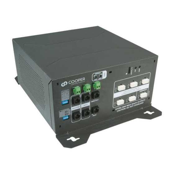
Distributed Low-Voltage Power System Installation Manual Specifications 120-277VAC (50/60 Hz) Input Voltage Input Current (amps) Normal Power EM Power Input Single Panel Input only Input (LVCM-03-100-03 or wiring both normal and EM inputs together) 120VAC 277VAC 120VAC 277VAC 120VAC 277VAC LVPM-03-100-03-1E LVPM-03-100-03 (no EM input) - Page 6 Distributed Low-Voltage Power System Installation Manual 600W Low-voltage power module 300W Low-voltage power module ote: The same functions are available in both the 600W and 300W models. The only difference is total available power. 16.2” (41.2 cm) 11.8” (27.9 cm) 11.5”...
-
Page 7: Installation
Distributed Low-Voltage Power System Installation Manual Installation The low-voltage power module is a plenum rated passively cooled device designed to be mounted above the ceiling in or near the space to be powered and controlled. Low-voltage power modules must be installed in one of two orientations (as shown) for proper cooling and to maintain system warranty coverage. -
Page 8: Technical Details
Emergency output to FULL ON. Inside the unit, there is a metal divider to keep the Normal load separate from the Emergency load. If the DLVP unit being installed does not require an emergency load, the divider can be removed and wired to create an ALL NORMAL connection. -
Page 9: Power Supply Connection
Many popular and energy efficient models of LED light fixtures are available for the Distributed Low-Voltage Power System. Consult www.cooperlighting.com for the most current model availability. Specifications For specifications of specific Cooper Lighting Solutions low-voltage light fixtures, consult www.cooperlighting.com. www.cooperlighting.com page 9... -
Page 10: Fixture Connection
Installation Manual Fixture Connection Connect DLVP low-voltage light fixtures to any available low-voltage output on the low-voltage power module using the low-voltage cable as shown below. If emergency power input is being used with the LVPM-03-100-03-1E or LVPM-06-100-03-1E power module, the emergency fixtures should be wired to low-voltage output #3. - Page 11 Whiteboard Raise Lower All Off ote: DLVP does not support the Quiet Time function found on some wallstations. ote: Toggle buttons on wallstations toggle between OFF and the last lighting command for that zone / scene. Specifications Voltage 24 VDC supplied from low-voltage power module...
- Page 12 Distributed Low-Voltage Power System Installation Manual Installation Mount wallstations to a single or multi-gang wallbox with a minimum internal depth of 2 inches (51mm). front cover inner plate main body Connection Using pre-terminated control cables, connect a wallstation(s) to a WALL port on the low-voltage power module as shown. Up to 12 wallstations may be daisy chained together and connected to a low-voltage power module (total for BOTH ports).
- Page 13 32° F to 104° F (0° to 40° C) For indoor use only. ote: Not for use with vacancy sensors (DLVP requires occupancy sensors and the system can be placed in vacancy mode) ote: The low-voltage power module connects to low-voltage Greengate occupancy sensors, through the OCC-RJ45 Input/Output.
- Page 14 Distributed Low-Voltage Power System Installation Manual Installation Ceiling Sensor Installation OAC sensors can be mounted to the ceiling, junction box or round fixture with raceway. ote: Optimum mounting height is 8-10 feet. • Do not mount over 12 feet. • Mount at fixture height to avoid obstructing view.
- Page 15 Distributed Low-Voltage Power System Installation Manual Wall/Corner Installation OAWC sensors can be mounted to the ceiling, junction box, octagon box or round fixture with raceway. ote: Optimum mounting height is 8-10 feet. • Do not mount over 12 feet. • Mount at fixture height to avoid obstructing view.
- Page 16 Distributed Low-Voltage Power System Installation Manual Connection The low-voltage power module is capable of powering up to two (2) total occupancy sensors. Sensors connect using the OCC-RJ45 input/output device and pre-terminated control cables. Once the sensor is mounted, attach the OCC-RJ45 input/output device to the sensor leads matching the wire colors to the label on the input/output device as shown.
- Page 17 Distributed Low-Voltage Power System Installation Manual Daylight Sensor (open loop) Description The low-voltage power module connects to one open-loop daylight sensor (DSRC-FMOIR) for multi-zone daylighting control. The open-loop daylight sensor adjusts the light level in the space based on natural light. The open-loop daylight sensor controls all three (3) zones in the low-voltage power module.
- Page 18 Distributed Low-Voltage Power System Installation Manual Installation The open-loop daylight sensor can be mounted to a ceiling tile or fixture using the threaded post and locking washer in materials up to a 0.75” thick. The accessory mounting bracket (DSCM-MT) allows the open-loop daylight sensor to be mounted to a hard wall. •...
- Page 19 Distributed Low-Voltage Power System Installation Manual Connection One (1) DSRC-FMOIR daylight sensor may be connected to the low-voltage power module using only the GGRC-COUPLER and pre- terminated control cable to one (1) of the sensor ports as shown. Once the daylight sensor mounting area is prepared, attach the GGRC-COUPLER to the sensor.
- Page 20 Distributed Low-Voltage Power System Installation Manual BMS / Egress Output Connect the OCC-RJ45 Input/Output Device to the BMS system. Use 18 AWG unshielded, 2 conductor twisted pair wiring for connection. Maximum distance must not exceed 1000 ft. (300m). Closure will be made across the Blue and Red terminal locations. Connect a pre-terminated control cable between the REC/BMS/OUT RJ45 port on the low-voltage power module and to one of the ports on the OCC-RJ45 ports.
- Page 21 Distributed Low-Voltage Power System Installation Manual Receptacle Rated Switchpack Description The Receptacle rated Switchpack includes a 20A relay for ON/OFF control of connected outlets. The Receptacle Rated Switchpack connects to the low-voltage power module to provide energy efficient control of receptacles. Controlled receptacles will switch OFF when occupancy sensor(s) no longer sense motion (after occupancy hold time expires).
- Page 22 All line voltage connections are made via pigtails with approved connectors. ote: Connect the black supply lead to the power source. ote: For details on receptacle rated switchpack operations, see DLVP Time Clock/Occupancy State section switchpack page 22 www.cooperlighting.com November 2019...
- Page 23 Distributed Low-Voltage Power System Installation Manual Connecting one switchpack: Connecting multiple switchpacks: DEFAULT DEFAULT HIGH HIGH DEMAND CLOCK ALERT DEMAND CLOCK ALERT 1 2 3 4 5 1 2 3 4 5 BMS/OUT LOW-VOLTAGE OUTPUTS BMS/OUT LOW-VOLTAGE OUTPUTS SENSORS WALL SUITABLE FOR CLASS 2 WIRING SENSORS WALL...
- Page 24 Distributed Low-Voltage Power System Installation Manual System Settings and Configuration Low-Voltage Power Module Settings DEFAULT HIGH Low-voltage power modules may be configured to satisfy the desired DEMAND CLOCK ALERT control intent of the many spaces via DIP switches located on the low 1 2 3 4 5 voltage panel as shown.
-
Page 25: Required Components
Distributed Low-Voltage Power System Installation Manual Scene Wallstation Programming Each scene button can be programmed with user specified On/Off and dimmer settings. Using the personal remote (LVHH-02) and daylight sensor (DSRC-FMOIR or fixture integrated sensors) the user can define and save up to six (6) scenes to be recalled later from the scene buttons on the wallstation or the personal remote. - Page 26 Distributed Low-Voltage Power System Installation Manual Light Fixture Zone Assignment On the back of every low-voltage light fixture in the area where the low-voltage lighting cable connections are made are DIP switches for setting a fixture’s zone. By default, any switch configuration results in zone 1 assignment, unless zone 2 or zone 3 are specifically set as below: If no specific zone is selected via ote:...
- Page 27 Distributed Low-Voltage Power System Installation Manual Adjusting the High and Low End Trim High and low trims can be adjusted to suit the needs of the user. High end trim allows the maximum light level to be turned down to a more comfortable level and reap additional energy savings.
- Page 28 Distributed Low-Voltage Power System Installation Manual Alternate Voltage Switchpack If an application requires mixed (class 1 and class 2) voltages, an alternative voltage switchpack may be connected to the low-voltage power module. Any Greengate switchpack may be wired to an OCCRJ45 Input/Output Device, allowing loads powered by 120 VAC, 240 VAC, 277 VAC, and 347 VAC circuits to be controlled.
-
Page 29: Time Clock
Overview The DLVP low-voltage power module provides an onboard time clock input, that can be used to control lighting normally via time clock or implement partial on/ partial off controls. The low-voltage power module provides inputs for an external dry contact closure. - Page 30 Distributed Low-Voltage Power System Installation Manual DLVP Time Clock / Occupancy State Settings Space Condition Time Clock Mode Partial On Motion Sensor No Motion Sensor Status (DIP - 1) (DIP - 2) Occupied Unoccupied Manual Button Press No Button Press...
-
Page 31: Demand Response
Leave the room and wait approximately one minute for the lighting to turn OFF. If lighting does not turn OFF, refer to “DLVP System Troubleshooting”. Sensors will automatically exit test mode after a period of 5 to 10 minutes (timing is dependent on sensor model) and begin automatically adjusting based on occupancy patterns. - Page 32 Distributed Low-Voltage Power System Installation Manual Turn the high end trim adjustment dial counter-clockwise in small increments until the light level is at the desired maximum level. Turn the low end trim dial clockwise then fully counter clockwise. The light level in the room will go full dim. Turn the low end trim dial clockwise in small increments until the light level is noticed increasing in the monitored space, then turn the dial slightly counter clockwise from where this change begins.
-
Page 33: Occupancy Sensors
LVHH-01 remote control to indicate that the controller is in Commissioning Mode. Under normal operation, the daylight sensor LEDs will not flash. Wallstations Quiet Time: Not supported with the DLVP system. General Whiteboard Wallstation with Quiet Time... - Page 34 Distributed Low-Voltage Power System Installation Manual Reset Open-Loop Daylight Levels Adjustments to default light levels are done using the open loop daylight sensor portion of the programming remote (LVHH-01). The remote control contains zone level buttons 1, 2 and 3, which correspond to zones 1, 2 and 3 on the low-voltage power module. With open-loop daylighting, zone 1 should be the zone closest to the window, while zone 3 is the furthest into the space.
-
Page 35: How It Works
Lighting will remain at the specified target level until no motion is detected for the full delay time (default value is 20 minutes). At that point, the space is considered to be unoccupied. ote: See the DLVP Time Clock / Occupancy State section to define occupancy driven actions. Using the Personal Remote (LVHH-02) - Page 36 Distributed Low-Voltage Power System Installation Manual Using the Programming Remote (LVHH-01) Open Loop Sensor Sensor Range Toggle Zones (manual control) High Direct Sun • Use the Z1, Z2, & Z3 buttons to manually toggle 2 Blinks = Low 3 Blinks = High each zone ON/OFF 4 Blinks = Direct Sun Daylight Gains...
- Page 37 The ID button is used to used to verify the current sensor daylight range setting of the external open loop sensor – see Verify and Set the External Open-Loop Daylight Sensor Range section for more details DLVP System Troubleshooting Lights will not turn ON...
- Page 38 Distributed Low-Voltage Power System Installation Manual Lights turn OFF unexpectedly Issue Possible Causes Suggestions Lights will not The controller senses that there is an Verify that the occupancy sensor LEDs are flashing when motion is occurring. remain ON occupancy sensor connected but is Make sure that the occupancy sensor coupler is connected to the correct wires from the (Lights turn not seeing an occupied signal from the...
-
Page 39: Miscellaneous Issues
Distributed Low-Voltage Power System Installation Manual Lights turn ON Daylighting Daylight levels may not be correct for the space. but remain at Using the personal remote (LVHH-02) or a connected wallstation, press the lower button to full bright level ensure the light level can go lower. Use the programming remote (LVHH-01) to adjust the daytime occupied light level. - Page 40 Veuillez consulter le site www.cooperlighting.com pour obtenir les conditions générales. Garantías y Limitación de Responsabilidad Visite www.cooperlighting.com para conocer nuestros términos y condiciones. Cooper Lighting Solutions 1121 Highway 74 South © 2020 Cooper Lighting Solutions Peachtree City, GA 30269 All Rights Reserved. P: 770-486-4800 www.cooperlighting.com...
Need help?
Do you have a question about the DLVP and is the answer not in the manual?
Questions and answers