Table of Contents
Advertisement
Quick Links
RESI®
Datum:
RESI
Version:
Informatik &
Bearbeitet von:
Automation
Geprüft von:
GmbH
Geprüft von:
Great care has been taken in the creation of the text, illustrations and
program examples in this manual. RESI Informatik & Automation
GmbH company, the editors and publishers accept no responsibility
for any inadvertent omission of entries or for typographical or other
errors herein. Nor can they be held responsible or liable for
consequences arising from any errors herein.
This manual may not be copied in part or whole in any form including
electronic media without the written consent of RESI Informatik &
Automation GmbH. Neither may it be transferred in any other
language suitable for machines or data processing facilities. Also
rights for reproduction through lecture, radio or television transmission
are reserved.
This documentation as well as the corresponding software are subject
to copyright law and protected by RESI company. All rights reserved.
Copyright 2009-2015 RESI Informatik & Automation GmbH
10.02.15
Kunde:
03.40
Titel:
DI HC SIGL
DI HC SIGL
Projekt:
-
RESI-DALI-PS
Manual RESI-DALI-PS
Seiten
11
Advertisement
Table of Contents

Subscribe to Our Youtube Channel
Summary of Contents for Resi DALI-PS
- Page 1 This documentation as well as the corresponding software are subject to copyright law and protected by RESI company. All rights reserved. Copyright 2009-2015 RESI Informatik & Automation GmbH 10.02.15...
-
Page 2: History
RESI® History Date Editor Description 14.02.15 DI HC Sigl First version Datum Seite Manual RESI-DALI-PS Titel: 14.02.2015... -
Page 3: Table Of Contents
CONTENTS ................................. 3 IMPORTANT SECURITY NOTES .......................... 4 GENERAL INFORMATION ............................. 6 MOUNTING AND CONNECTIONS ........................8 ................................8 SSEMBLING & LED ............................... 9 LAMPS ..............................10 IRING DIAGRAM SPECIFICATIONS ..............................11 ................................11 IMENSIONS Datum Seite Manual RESI-DALI-PS Titel: 14.02.2015... -
Page 4: Important Security Notes
Operating our device close to equipment, which do not comply with EMC directives, can influence the functionality of our device, leading to malfunction or in worst case to a breakdown of our device! Datum Seite Manual RESI-DALI-PS Titel: 14.02.2015... - Page 5 Dimensions of the enclosures or enclosures accessories may show slight tolerances on the specifications provided in these instructions! Modifications of this documentation is not allowed! In case of a complaint, only complete devices returned in original packing will be accepted! Datum Seite Manual RESI-DALI-PS Titel: 14.02.2015...
-
Page 6: General Information
A DALI network consist out of a maximum of 64 lamp ballasts with DALI interface, a DALI power supply and at least one DALI master to send commands to the DALI lamps (e.g. Our RESI-DALI-MODBUS or RESI- DALI-ASCII converter fulfill this task). Out power supply RESI-DALI-PS offers true 200mA to supply the DALI bus line with power. - Page 7 JYStY 2 x 1,5mm² DALI output current Max. 200mA Cable connection Via clamps Galvanic insulation to primary power supply LED indicator Clamps Clamp wire cross section Max. 1,5 mm² Tightening torque Max. 0.5Nm CE conformity Datum Seite Manual RESI-DALI-PS Titel: 14.02.2015...
-
Page 8: Mounting And Connections
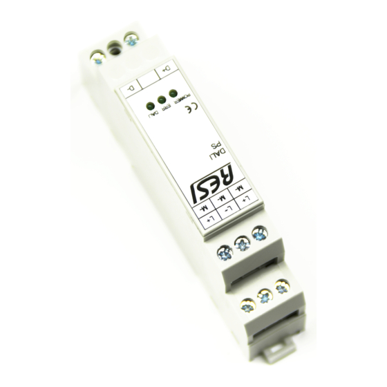
Mounting and Connections Assembling Our RESI-DALI-MODBUS converters and our RESI-DALI-PS power supplies are designed for mounting on a 35mm DIN-EN50022 rail. Please note, that there are symbol photos used in the mounting pictures below. At first, put the converter with the top side on the DIN rail (1). -
Page 9: Clamps & Leds
DALI system DALI DALI activity LED, is permanent on. When transmitting a DALI telegram the LED switches off of a few milliseconds. Table: Description of connectors of the RESI-DALI-PS module Datum Seite Manual RESI-DALI-PS Titel: 14.02.2015... -
Page 10: Wiring Diagram
RESI® Wiring diagram Power Supply +24V= Output: 24Vdc DALI Lamp System DALI- Max 64 DALI lamps <200mA DALI+ Illustration: Wiring diagram of the RESI-DAI-PS power supply Datum Seite Manual RESI-DALI-PS Titel: 14.02.2015... -
Page 11: Specifications
Enclosure dimensions L x W x H (mm) 17,5 x 90 x 58 Weight 60 g Colour Grey RAL7035 Material PA - UL 94 V0 Protection class IP20 based on DIN 40050/EN 60529 Table: Data of enclosure Datum Seite Manual RESI-DALI-PS Titel: 14.02.2015...
Need help?
Do you have a question about the DALI-PS and is the answer not in the manual?
Questions and answers