Advertisement
Quick Links
Advertisement

Summary of Contents for YIDIMU Panther
- Page 1 YIDIMU LCD 3D Printer User Manual...
- Page 2 Precautions Please keep in mind the following precautions during assembly and use. Failure to follow these warnings may result in damage to the machine or even personal injury. 1. There is a FEP film at the bottom of the resin vat. It can’t be pierced or scratched by sharp objects.
- Page 3 Contents 1.Technical Specification ............4 2.Packing List ................5 3.Product Overview ..............6 4. Machine Testing..............11 5. Software Installation and Operation Instructions..30 6. Assembly and Leveling Instructions........ 36 7. Printing Process Instructions..........40 8. FAQ and Machine Maintenance........41 9. Warranty and Service............42...
- Page 4 Technical Specification Print Parameters: Build Volume:120(L)x 65(W)x165(H)mm Layer Thickness:0.025mm/0.05mm/0.1mm Print Speed:20mm/h(Z axis XY Resolution:47um Machine Parameters: Machine Size:220(L)x200(w)x426(H)mm Packaging Size:292(L)x272(w)x622(H)mm Software Parameters: Printing Software:CHITUBOX File Format:STL Adaptive System:win7 above Physical Parameters: Consumable parameters: 405nm UV-resin Connection method:USB Print Light Source:UV led Input Voltage:220V AC /47-63 Hz Rated Power:85W...
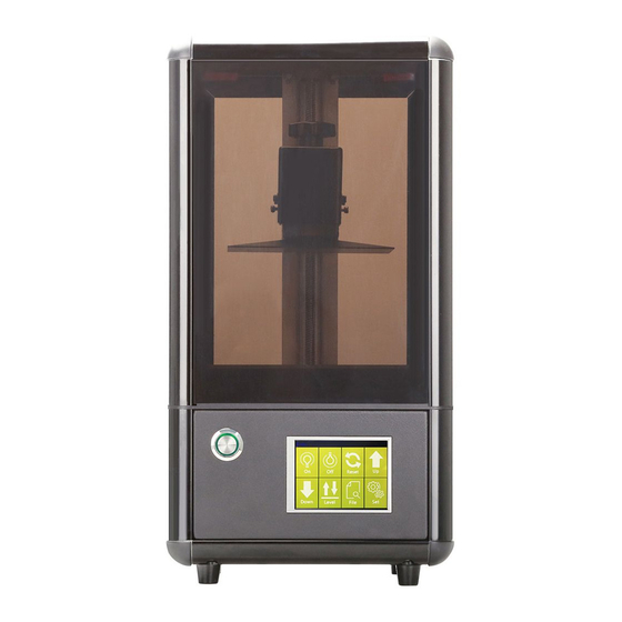
- Page 6 Product Overview...
- Page 7 Print test The machine must be tested before printing for the first time. The test content includes: Z-axis reset, switch light, switch between Chinese and English interface. First plug the power cord and turn on the AC power switch, then turn on the switch diagram of the machine. After the boot is completed, the interface is as shown.
- Page 8 contact the company for help. (Do not install the tray on the machine when testing the Z-axis for the first time. If the screen is damaged due to the tray problem, it will not be repaired!) (Click manually) ( ) Click the up arrow or down arrow to check if the Z axis is normal.
- Page 9 screen of the machine displays the following figure (4). If it cannot be displayed normally, the power should be disconnected and contact the company for assistance. Click the “back arrow” on the touch screen to observe the machine. The LCD screen is dark. If it cannot be darkened, you should disconnect the power supply and contact the company for assistance.
- Page 10 (Click the next step) ( ) Check whether the light is normal or not (3)Change the screen from Chinese to English First click on "System" and then click on the language in the picture to switch to English (Chinese vice versa)
- Page 11 (Click“Language”) (Change Options)...
- Page 12 Software installation and operation instructions 1.1 Install CHITUBOX slicing software First find "ChiTuBox64Install_1.4.0" in the U disk (As follows). Double-click open "ChiTuBox64Install_1.4.0" installation application, select the software display language. Click “ok” and Click the next step.
- Page 13 Click “I Agree”. Select software installation location.
- Page 14 Installation is complete, choose whether to run the software immediately. 1.2 Interface introduction...
- Page 15 (Menu Bar) 1.2.1 Open file: open the file you need to operate. 1.2.2 Save file: store the operation file that has been performed. 1.2.3 Screenshot/recording: watermarking the screen, screen recording, screen capture (1)Watermark: Check the date on the watermark (real time date), author & other (the gear can be edited).
- Page 16 the platform. 1.2.7 Hollow: Internal hollow or external hollow, wall thickness and accuracy required. Digging holes: need to set the shape and size, 1.2.8 whether to keep the hole, add a hole. 1.3 Model editing 1.3.1 Moving model (1) Move on the X, Y, and Z axes: directly place the cursor in...
- Page 17 the number box and scroll the mouse. You can place the model directly on the backplane, center it, and reset it. 1.3.2 Rotation model (1) Rotate on the X, Y, and Z axes respectively: Click once to rotate 15° in the positive direction of X/Y/Z; Click once to rotate 15°...
- Page 18 hold down the left mouse button to move (red-X, green-y, blue-Z) 1.3.3 Zoom model Scale on the X, Y, and Z axes respectively: (1) The cursor can be zoomed by scrolling the mouse over the number box. (2) When the scale is locked, no matter which axis is placed on the scale, the other two axes will become larger and smaller according to the scale.
- Page 19 (1) X mirror: mirror the current model with the X axis as the axis of symmetry (2) Y mirror: mirror the current model with the y-axis as the axis of symmetry (3) Z mirror: mirror the current model with the Z axis as the axis of symmetry 1.4 Mouse operation (operation in Chinese layout) 1.4.1 Left click: Click on the model to select the model to...
- Page 20 1.4.2 Left button long press Left-click and long-press model to move the model on the current horizontal plane ( 2 ) Left-click on the platform or blank space to drag the platform and model in all directions. 1.4.3 Right click and hold: right click to rotate the platform 1.4.4 Mouse scroll wheel: scales the entire platform and model 1.5 Scenes 1.5.1 Drag the scene: long press the left mouse button...
- Page 21 1.5.4 Front view: Click to make the scene and model right front view facing the user .5.5 Front view angle/ perspective view: for the current model can be forward view, perspective view switch 1.5.6 Top view / left view / front view: T - top view; L - left view;...
- Page 22 1.6 Simple Setting 1.6.1 File list: All models on the platform will be arranged in the file list, which can be edited or deleted by the full selection/single selection model. 1.6.2 Slice Setting...
- Page 23 <Import>: Import the saved machine configuration parameters (the cfg file also contains support parameters); Special attention: There is already a set configuration parameter file in the U disk. You do not need to set any parameters for direct import, you can directly print the model!!! (Configuration parameter file)...
- Page 24 <name>: The name of the machine, which can be directly entered into the text for custom naming; <resolution>: the resolution of the projector or LCD screen, this parameter directly affects the dimensional accuracy of the print; <lock ratio>: Under normal circumstances, the ratio of the molding size XY = the resolution ratio, that is, the locking ratio;...
- Page 25 <Resin type>: Different resin types have different parameters, and some resin and corresponding parameters recommended by the company have been integrated; <Resin density>: the density of the resin used to calculate the quality; <resin price>: the cost of the resin used to calculate the cost; (3)Print...
- Page 26 <layer thickness>: the thickness of each layer of the model is generally 0.025/0.05/0.1mm <Number of bottom layers>: The number of layers to be cured at the bottom of the model. In order to better adhere to the platform, the parameters of the bottom layer need to be separately set.
- Page 27 (4)Fill <fill structure>: selection of fill type inside the model, such as mesh structure, etc. (5)Gcode...
- Page 28 <Start>: Preprocessing command executed at the beginning of printing (customizable) <Interlayer>: Print processing commands executed at each layer in progress (customizable) {image} The name of the resulting exposure image {raise_pos} corresponds to the raised position, which is an absolute coordinate value, value = exposure position + lift height {raise_speed} is the lifting speed, the lifting speed = the bottom lifting speed or the lifting speed...
- Page 29 <End>: Processing command executed at the end of printing (customizable) {machine_height} corresponds to the height of the machine size (Can understand, no effect on printing) (6)Advanced <Bottom Light Intensity PWM>: The intensity of the light source when printing the bottom layer (some printers support this command) <Light intensity PWM>: The intensity of the light source when printing in the normal layer (some printers support this command)
- Page 30 1.6.3 Slice Slice: Click on the slice to start the model slice processing (select the corresponding parameters for slicing) 1.6.4 Slice preview: Support cross-section and solid model preview at the same time (automatically jump to slice preview after clicking slice)
- Page 31 1.7 Support setting 1.7.1 Z-axis lift height (default is 5mm), customizable 1.7.2 Support Setting(Refresh the data, fold Expand ) (1) Select the size of the support, which is available in fine, medium and thick. (2) Top: Set the top of the support, there are default values, users can change according to their own preferences.
- Page 32 change according to their own preferences. (5) Bottom line: Set the bottom line, there are default values, users can change according to their own preferences. 1.7.3 Automatic support( Refresh the data, fold Expand ): The data of the auto-support is set and has default values, which can be changed according to your own preferences.
- Page 33 model 1.7.6 Edit Support: Manually edit existing support anywhere on the model 1.7.7 Remove all: remove all existing support Assembling the printer and its leveling instructions (1) Check the appearance of the outer box of the 3D printer for scratches, bumps, etc.
- Page 34 (1) Loosen the tray fastening screw (Special note: the leveling has been completed before leaving the factory, the first print can ignore this step!!!) (2)Raise the Z axis to the middle...
- Page 35 (3)loading tray (4)Tighten the tray bracket fastening screws...
- Page 36 (5)Auto-leveling 01.Place A4 paper on the LCD screen 02.Auto-leveling...
- Page 37 (6)Tighten the screws (Hold the tray firmly with one hand to ensure that the current position of the printing platform does not move, and tighten the screws No. 2 and No. 5 with the other hand.)...
- Page 38 (Then use the wrench to tighten the remaining four screws one after the other.) (7)Install Resin Vat 01.Raise the Z axis in the middle (there is a tutorial in front) 02.Clean the LCD screen and the flute release film with a clean cloth...
- Page 39 03.Put the trough on the LCD screen 04.Insert the slot fastening screw and tighten (8)Installation leveling completed...
- Page 40 Printing process and post-processing instructions (1) Preparation before printing (including machine testing, model slicing). (2) After the model is sliced, save it to the USB flash drive, and then insert the USB flash drive into the USB port of the machine. (1)Add 1/4-1/3 resin to the trough.
- Page 41 (2)Printing operation (Click Print) (Check the model you want to print) (Print interface) (Print layer sectional view) (3)Cover the printer cover Note: 1. Be sure to cover the cover during printing to avoid air pollution...
- Page 42 and other damage. 2. Protect the machine from working out of reach of children. (4)Finishing the print and removing the cover (7) Take out the tray 01. Loosen the tray bracket fastening screw 02. Pull out the tray 03. Turn over the desktop...
- Page 43 The model is placed in a 405-wavelength UV curing chamber for 3-5 minutes to achieve the best results on the surface of the model (not available, you can go to the official website of YIDIMU) Note: In the case of incomplete printing or printing failure, the resin in...
- Page 44 resin of the trough with a filter after each printing, and wipe the residue with a dust-free cloth. Clean, prevent the next print residue will crush the 2K screen,) Machine maintenance (1) The power must be cut off during maintenance; (2) Wiping the resin tank and the printing platform with a dust-free cloth;...
- Page 45 Quality assurance after-sales service Quality Assurance: Behind every product is the commitment of EDIM Smart, and our rigorous parts processing standards and assembly inspection processes ensure that each product is a qualified, high quality product. after-sale warranty: 1. Since the goods are received within 7 days, due to the problems caused by the quality of the products, we will bear the return shipping costs for your free replacement or repair.
- Page 46 5, release film, LCD is a consumable item is not covered by the warranty, the release film is generally replaced once every 15 days, frequently used for 5-7 days to replace, the LCD screen life is generally one to two months.
Need help?
Do you have a question about the Panther and is the answer not in the manual?
Questions and answers