Table of Contents
Advertisement
Quick Links
•
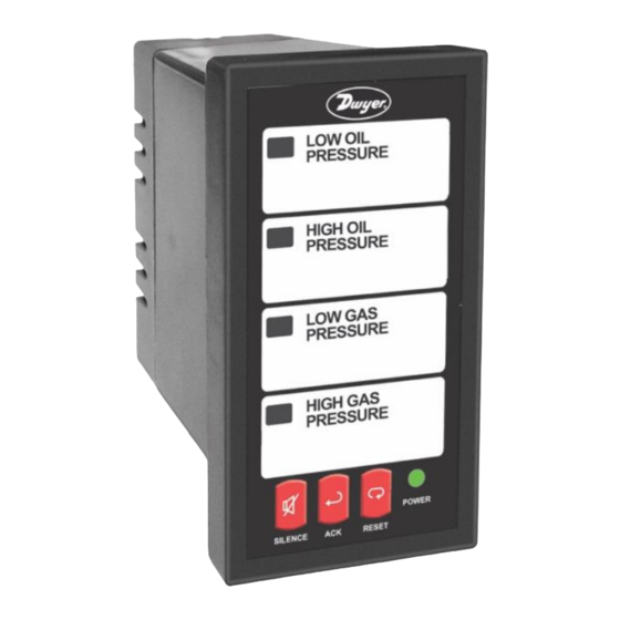
1/8 DIN Annunciators with NEMA 4X, IP65 Front
•
Switch, Transistor, and Logic Level Inputs
•
4 or 8-Point Monitoring
•
8 Field Selectable ISA Sequences Including First-Out
•
Multiple-Unit First-Out Indication
•
Free Custom Message Labels
•
Silence, Acknowledge, and Reset Functions
•
Sunlight Readable Indication
•
Shallow Depth Case Extends Only 3.6" (91 mm) Behind Panel
•
Isolated 24 VDC @ 200 mA Transmitter Power Supply (AC Models)
•
2 SPDT Relays for Alarm Activated Devices
•
Operating Temperature Range: -40 to 65°C (-40 to 149°F)
•
UL & C-UL Listed. E160849; 508 Industrial Control Equipment
•
Input Power Options: 85-265 VAC / 90-265 VDC or 12-36 VDC / 12-24 VAC
•
Built-in Internal 85 dB Horn with Silence Pushbutton
•
3-Year Warranty
DWYER INSTRUMENTS, INC.
P.O. BOX 373 • MICHIGAN CITY, IN 46360, U.S.A.
AN24 & AN28 Annunciators
Instruction Manual
Phone: 219/879-8000
dwyer-inst.com
Fax: 219/872-9057
e-mail: info@dwyermail.com
Bulletin: P-AN2
Advertisement
Table of Contents

Subscribe to Our Youtube Channel
Related Manuals for Dwyer Instruments AN24 Series

Summary of Contents for Dwyer Instruments AN24 Series
- Page 1 Input Power Options: 85-265 VAC / 90-265 VDC or 12-36 VDC / 12-24 VAC • Built-in Internal 85 dB Horn with Silence Pushbutton • 3-Year Warranty DWYER INSTRUMENTS, INC. Phone: 219/879-8000 dwyer-inst.com P.O. BOX 373 • MICHIGAN CITY, IN 46360, U.S.A. Fax: 219/872-9057...
-
Page 2: Introduction
Ordering Information could result in personal injury or property loss. Anyone using this product for such applications 85-265 VAC* 12-36 VDC* does so at his/her own risk. Dwyer Instruments, Description Model Model Inc shall not be held liable for damages resulting from such improper use. -
Page 3: Table Of Contents
AN24 & AN28 Annunciators Instruction Manual Table of Contents Introduction ......................2 Ordering Information ................... 2 Quick Setup Guide ....................5 Sequence Selection ..................5 NO/NC Inputs ....................5 Basic Connections ..................5 Specifications....................... 5 General ......................6 Input ........................6 Relays ....................... - Page 4 AN24 & AN28 Annunciators Instruction Manual ISA Sequence F1A ..................17 ISA Sequence F3A ..................18 Input Follower Indication ................19 ISA Sequence M ..................... 19 ISA Sequence F1M ..................19 ISA Sequence F2M ..................20 Table of Figures Figure 2. Panel Cutout and Mounting ..............7 Figure 3.
-
Page 5: Quick Setup Guide
AN24 & AN28 Annunciators Instruction Manual Quick Setup Guide Basic Connections The following overview details how to set up the All connections are made to removable screw annunciator for most common uses. terminal connectors located at the rear of the instrument. -
Page 6: Specifications
AN24 & AN28 Annunciators Instruction Manual Specifications Input Input Types NO or NC switches: No external Except where noted all specifications apply to operation at +25°C. excitation required General Open collector transistor (NPN): Open circuit voltage approximately AN24; Four red LED channel/point Display 3.3 VDC indicators. -
Page 7: Compliance Information
AN24 & AN28 Annunciators Instruction Manua Compliance Information Installation There is no need to remove the instrument from its Safety case to complete the installation, wiring, and setup. UL Listed USA and Canada UL 508 Industrial Control Equipment Unpacking UL File Number E212517 Front Panel UL Type 4X, NEMA 4X, IP65;... -
Page 8: Dimensions
AN24 & AN28 Annunciators Instruction Manual Connectors Labeling Dimensions The connectors label, affixed to the instrument, shows All units: inches [mm] the location of all connectors available with requested configuration. 3.56" 4.18" (91mm) (106mm) Figure 4. Connector Labeling for AN24-1 2.50"... -
Page 9: Power Connections
AN24 & AN28 Annunciators Instruction Manual Open Collector NPN Transistor Power Connections Each transistor collector is connected to a separate Power connections are made to a two-terminal input channel and all emitters connected to common. connector labeled POWER. See Connectors Labeling All channels are factory set for transistor inputs on page 8. -
Page 10: Switching Inductive Loads
AN24 & AN28 Annunciators Instruction Manual Multiple Unit First-Out Indication Switching Inductive Loads Connections The use of snubbers to suppress electrical noise is strongly recommended when switching inductive loads Multiple AN28 and AN24 units can keep a single first- to prevent disrupting the microprocessor’s operation. out channel indicated for all connected units. -
Page 11: Setup And Programming
AN24 & AN28 Annunciators Instruction Manua Setup and Programming Pushbutton Descriptions SILENCE Overview Silences the audible alarm without affecting the indication sequence states. This pushbutton may be There are no jumpers involved in the setup process disabled (see Audible Horn Enable/Disable, page 14). of the annunciator. -
Page 12: Annunciator Sequence Selection
AN24 & AN28 Annunciators Instruction Manual Annunciator Sequence Normally Open/Normally Closed Selection Input Setup The alarm sequence is selected with the DIP switch Each input channel is independently programmed for located above the signal connector. a normally open or normally closed input. All channels are initially programmed at the factory for normally Changing sequences while the unit is on will restart open inputs. -
Page 13: No/Nc Programming Example
AN24 & AN28 Annunciators Instruction Manual Relay Operation NO/NC Programming Example The following is an example of NO/NC setup. Input Relays 1 and 2 have standard functionality as defined channel 1 and 2 are changed from the default settings below. of NO to be NC inputs. -
Page 14: Relay Fail-Safe Programming Example
AN24 & AN28 Annunciators Instruction Manual Relay Operation Overview Relay Fail-Safe Programming Example The following figure illustrates the operation of the The following is an example of relay fail-safe setup. relays. Relays 1 and 2 are changed from the default settings of normal operation to fail-safe operation. -
Page 15: No Lock-In Sequence Option
AN24 & AN28 Annunciators Instruction Manua Note: LED 1 and 2 are used for relay fail-safe setup Silence Pushbutton (see page 13), and LED 3 is used for silence Enable/Disable pushbutton enable/disable (see page 14). Press and hold ACK and RESET for 3 The unit will automatically leave setup mode if steps seconds until all LEDs cycle, then release. -
Page 16: Full Sequence Descriptions
AN24 & AN28 Annunciators Instruction Manual Full Sequence Descriptions ISA Sequence A The following section describes the operation of the Acknowledge Pushbutton and Automatic Reset various sequences available in the Series AN24/AN28 alarm annunciator. Momentary Alarm Maintained Alarm Condition Horn Condition Horn Features... -
Page 17: Isa Sequence F2A
AN24 & AN28 Annunciators Instruction Manual ISA Sequence F2A ISA Sequence F1A First-Out Indication with Acknowledge Pushbutton First-Out Indication with Acknowledge Pushbutton, No and Automatic Reset Lock-In of Subsequent Alarms, and Automatic Reset Momentary Alarm Momentary Alarm Condition Horn Condition Horn Next Pt Next Pt... -
Page 18: Isa Sequence F3A
AN24 & AN28 Annunciators Instruction Manual Maintained Alarm (ACK before RESET) ISA Sequence F3A Condition Horn First-Out Indication with Acknowledge Pushbutton, Next Pt Automatic Reset, and First-Out Reset Pushbutton Normal Alert Intermittent Fast Flash Sequence F3A Switch Positions Flash ACK Pushbutton Acknowledge Slow Flash Steady... -
Page 19: Input Follower Indication
AN24 & AN28 Annunciators Instruction Manua Input Follower Indication ISA Sequence F1M Switch Simple Indication First-Out Indication with Acknowledge and Reset Positions Condition Horn Pushbuttons, and No-Lock-In of Subsequent Alarms Normal Momentary Alarm Alert Steady Condition Horn Normal Next Pt Normal ISA Sequence M Alert... -
Page 20: Isa Sequence F2M
AN24 & AN28 Annunciators Instruction Manual ISA Sequence F2M Sequence F2M Flow Chart First-Out Indication with Acknowledge and Reset Pushbuttons Condition Normal Pt LED Momentary Alarm Next Pt LED Condition Horn Horn Next Pt Reset Alarm Condition Normal while Normal Alert Flash Steady... - Page 21 DWYER INSTRUMENTS, INC. Phone: 219/879-8000 dwyer-inst.com P.O. BOX 373 • MICHIGAN CITY, IN 46360, U.S.A. Fax: 219/872-9057 e-mail: info@dwyermail.com LIM158DW_B SFT043 Ver 1.0 & up 07/20...
Need help?
Do you have a question about the AN24 Series and is the answer not in the manual?
Questions and answers