Advertisement
Quick Links
Advertisement

Summary of Contents for Hanasis K-170D
- Page 1 K-170D User manual Safety precations Before use the product,please read this manual carefully.
- Page 2 Contents Bios Introduction Installation Extension Safety precaution guide Stand installation Adapter replacement Bios setting Product(K-170D) introduction Power connection - System adapter System basic & option Power on/off - Printer adapter Configuration Part name & Function Printer replacement System composition - Exterior design...
- Page 3 Precautions Contents Introduction Safety precautions ■ Please read the manual carefully to prevent any damage and injury then use the product properly. Caution Introduction Specification&Options When you install the product, please put the product on the stable table. Part name&Function When you put the product on the table, do not put the product on the steep table and waving area.
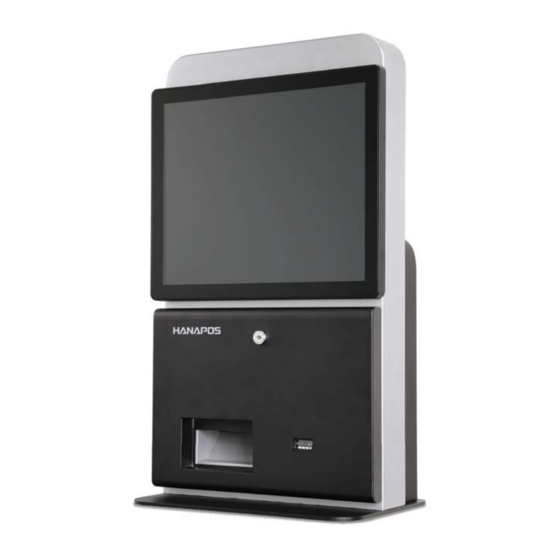
- Page 4 K-170D is tested fully to certify it's quality and durablity based on Hanasis' excellent technology. Part name&Function K-170D is applied gorgeous and emotional design and Barcode scanner and NFC can be installed as optional item K-170D complies with global standard certification.
- Page 5 Specification and Options Contents Introduction Specification and Options ■ Caution Basic specification Graphic & Touch screen Introduction Processor Intel® Celeron® J1800 Dual Core Chipset System on chip (SoC) (2.41 GHz 1M Cashe) Intel® Celeron® J1800 Quad Core (2.0 GHz 2M Cashe) Specification&Options Dispaly 17"...
- Page 6 Parts name and Product Function Contents Introduction Exterior design ■ Caution [ Front ] [ Rear ] Introduction Specification&Options Part name&Function ㆍ ㆍ Exterior design ㆍ Product Inside Rear cover ㆍ Product I/O Touch monitor ㆍ Product Iabel Installation Lock Usage Cable outlet - Power cable...
- Page 7 Parts name and Product Function Contents Introduction Product Inside ■ Please open the door after unlocking the locker by the key. (key : Rear cable outlet) Caution Introduction Specification&Options Part name&Function ㆍ ㆍ Exterior design ㆍ Product Inside ㆍ Product I/O ㆍ...
- Page 8 Parts name and Product Function Contents Introduction Interface ■ Caution Introduction [ Front ] [ Inner ] Specification&Options PWR Switch AC - IN Part name&Function ㆍ ㆍ Exterior design POWER ㆍ Product Inside ㆍ Product I/O LINE Internet COM1 COM2 -OUT HDMI COM3...
- Page 9 Operation is subject to the following two conditions: 1) this device may not cause harmful intererence, and 2) this device must accept any interference received, Installation including interference that may cause undesired operating. Model : K-170D Code : KK16P-BSNN4NSNN01 ROHS compliant Rating : DC24V...
- Page 10 Stand installation Contents Introduction Stand installation and Precautions ■ stand is optional item. Stand is heavy, Please watch out not to happen any falling accident Installation Exterior Stand installation Power connection Power on/off Stand bady Usage Screws X2 Extension Screws X4 Stand base Bios Screws X2...
- Page 11 Power connection Contents Power connection and Caution Introduction ■ stand is optional item. Stand is heavy, please watch out not to happen any falling accident. Installation [Stand] [Desk] Stand installation Power connection Power on/off 전원버튼 Power switch Usage Extension Bios Door Configuration Lock...
- Page 12 Power on/off Contents Introduction Power connection and Caution ■ Installation [ Power on ] [ Power off ] Stand installation ① Run the system by pushing the power button located inside the front door. While the system is operating, do not turn off the system forcibly, in ②...
- Page 13 Printer paper replacement Contents Introduction Printer paper replacement precautions ■ Installation ※ Please use proper printer paper diameter. ※ While the printing, please do not open printer cover. ※ Please get rid of paper roller after using up the paper. (Paper diameter = Ø80mm) Usage Printer paper replacement Extension...
- Page 14 Adaptor replacement Contents Introduction [ System adapter ] ■ Please use official adapter certified from supplier, do not try to connect other supplier's adapter. Installation Usage Screw(6ea) Extension System cover is heavy, please beware of falling accident is not happened. Adaptor replacement ㆍ...
- Page 15 Adaptor replacement Contents Introduction [ Printer adapter ] ■ Please use the power adapter provided from supplier.Please beware of connecting other power adapter. Installation ※ After replacing the new adapter, please watch out cable is not disturbed from other environmental factor. Usage Extension Screw ×2...
- Page 16 Product extension Contents Introduction Print replacement method ■ After replacing the new adapter, please watch out cable is not disturbed from other environmental factor. Installation Screw ×2 Usage Extension Printer cable Adaptor replacement Printer replacement Barcode scanner eplacement Printer cable System AS Bios Configuration...
- Page 17 Product extension Contents Introduction Barcode scanner replacement ■ After replacing the new adapter, please watch out cable is not disturbed from other environmental factor. Installation Usage Extension Adaptor replacement Printer replacement Barcode scanner eplacement System AS Screw ×2 Bios <Door inside> Configuration ①...
- Page 18 Product extension Contents Introduction System replacement ■ Before put the body on the floor, please clear the any dust or environmental factor being damaged touch panel. Installation Usage Screw(6ea) Extension While reassembly goes on, beware of losing the screws. Adaptor replacement ①...
- Page 19 BIOS Setting Contents Introduction Bios access ■ In order to access BIOS, keyboard should be connected in advance. Please refer to our website for better bios set-up understanding. Installation Bios include basical system setting,please watch out system operate improperly by wrong setting index. Usage 1.
- Page 20 System composition Contents DDR3L Introduction HDMI 1333MHz VCCM LVDS(2CH/24BIT) PS8625 Installation VCORE 1.8V 1.5V PCIe PWR PART LAN GbE(RJ-45) RTL8111F 3.0V 5.0V Usage 5VSB 3VSB SATA-II SATA-II Intel Celeron Extension BAY-TRAIL AUDIO ALC662 Bios USB2.0 USB2.0 X 6ea AUDIO AMP TOUCH (5-wire) EXC7700 Configuration...
- Page 21 Main board composition Contents Introduction Primary chipset and connector ■ ■ Installation Usage Extension Bios Configuration System composition Main board composition Main Jumper setting I/O Pin map Touch Panel Controller Pin Header FAN (CPU) Connector FAN (System) Connector CMOS Clear Jumper AT/ATX Mode Jumper SATA Combo Connector Reset Connector...
- Page 22 Main board composition Contents Introduction Primary chipset and connector ■ ■ Installation Usage Extension Bios Configuration System composition Main board composition Main Jumper setting I/O Pin map...
- Page 23 Main Jumper composition Contents Introduction Jumper usage setting ■ Jumper cap Please refer the next image for the specification by the jumper setting. Installation Usage Jumper pin #01/#02/#03 ① All block ② Open ③ 1-2 jumper block Extension CMOS innitialization ■...
- Page 24 I/O Pin map Contents Introduction COM 1 / 2 - Serial port (DSUB 9 Pin) ■ Installation Signal Description Usage Extension Bios Configuration COM Power System composition COM 3 / 4 port (RJ-45) ■ Main board composition Main Jumper setting Signal Description I/O Pin map ㆍ...
- Page 25 I/O Pin map Contents ■ MSR port (RJ-45) : COM5, USB7 Introduction Signal Description Installation VUSB 5.0V USB DM Usage USB DP Extension VUSB 5.0V Bios 8 8 8 8 Configuration System composition ■ HDMI port Signal Description Signal Description Main board composition TMDS Data2+ TMDS Clock Shield...
- Page 26 I/O Pin map Contents ■ LAN port (RJ-45 with LED) Introduction Signal Description MD0 (+) Installation MD0 (-) MD1 (+) Usage MD1 (-) MD2 (+) Extension MD2 (-) MD3 (+) 8 8 8 8 Bios MD3 (-) ■ USB 2.0 port (TYPE-A) Configuration Signal Description System composition...
- Page 27 I/O Pin map Contents ■ DC-IN (Power DIN-4) Introduction Signal Description Installation +12V Usage +12V Extension Bios ■ DC-OUT (JACK) Configuration Signal Description System composition +12V Main board composition Main Jumper setting I/O Pin map ㆍ ㆍ COM 1/2/3/4 ㆍ MSR, HDMI ㆍ...
- Page 28 17, Saneop-ro 155beon-gil, Gwonseon-gu Suwon-si, Gyeonggi-do, 16648, KOREA Direct. +82-70-4732-5264 Fax. +82-31-297-4381 Email. smkim@hanasis.com http://www.hanasis.com...
Need help?
Do you have a question about the K-170D and is the answer not in the manual?
Questions and answers