Table of Contents
Advertisement
Quick Links
Advertisement
Table of Contents

Summary of Contents for OZGENC MAKINA OMRM-136
- Page 1 M.S.K. MOTOR KOMPRESÖR MAKINA SAN. TIC. LTD. STI. Nilufer Organize Sanayi Bolgesi 113. Sk. No: 23 Nilüfer Bursa Turkey 16140 : +90 224 411 07 45 : +90 224 411 07 49 PRODUCT AND MAINTENANCE MANUAL CORNER CRIMPING MACHINE Model No. OMRM - 136 YOUR OZGENC DISTRIBUTOR IS:...
-
Page 2: Table Of Contents
INTRODUCTION CONTENT INTRODUCTION ..........................3 SAFETY MEASURES .......................... 4 SYMBOLS USED IN THIS MANUAL ................... 4 SAFETY INSTRUCTION ......................5 MACHINE DESCRIPTION ........................7 GENERAL VIEW ........................7 TECHNICAL DESCRIPTION ......................8 TECHNICAL SPECIFICATIONS ....................8 PACKAGE CONTENTS ....................... 8 INSTALLATION .......................... - Page 3 INTRODUCTION 7.3.2 OILS RECOMMENDED FOR LUBRICATOR USE ............... 28 TROUBLESHOOTING ........................29 WHAT TO DO IF A MALFUNCTION IS PRESENT..............29 PROBLEM – CAUSE – SOLUTION TABLE ................. 29 CIRCUIT DIAGRAMS ........................30 PNEUMATIC CIRCUIT ......................30 PARTS LIST ..........................31 10.1 MECHANICAL PARTS ......................
-
Page 4: Introduction
INTRODUCTION 1. INTRODUCTION We congratulate you on acquisition of the high-quality equipment. Undoubtedly, you have made a correct and well-founded choice, production of our company is the highly reliable product corresponding to the European quality standards. The equipment is simple in usage, has high consumer properties and will serve you long. -
Page 5: Safety Measures
SAFETY MEASURES 2. SAFETY MEASURES 1. Operation of the machine shall be performed by the operator only. 2. Operate the machine only after you have thoroughly understood all the designations and definitions pertaining to safety. 3. The operator, who did not read or understand this manual, may not work on or operate this machine. -
Page 6: Safety Instruction
SAFETY MEASURES 2.2 SAFETY INSTRUCTION ATTENTION! It is mandatory to read the manual and understand all rules and provisions. Keep the manual in a safe place. The manual shall be within easy reach in order to be consulted while servicing the equipment. The person performing the installation of the machine shall thoroughly read and understand this manual. - Page 7 SAFETY MEASURES Avoid jamming your hands between profile fixing cylinders and moving parts of the equipment. Do not open the protective covers until the machine is fully switched off. Only one operator shall work with the machine. The machine shall undergo regular maintenance and adjustment. Do not operate the machine if it is out of order.
-
Page 8: Machine Description
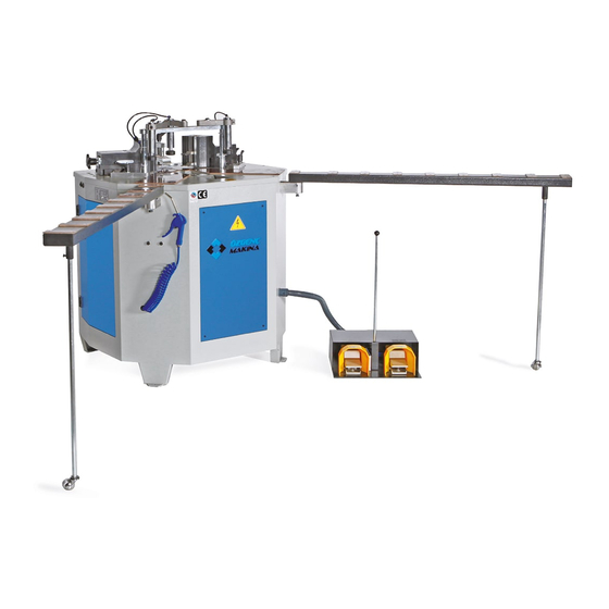
MACHINE DESCRIPTION 3. MACHINE DESCRIPTION 3.1 GENERAL VIEW ю ю ю Figure 3.1-1 General view 1. Corner crimping pedal. 2. Lock stop activation pedal. 3. Side stops. 4. Right crimping head. 5. Corner stop horizontal adjustment knob. 6. Corner stop vertical adjustment knob. 7. -
Page 9: Technical Description
MACHINE DESCRIPTION 3.2 TECHNICAL DESCRIPTION 2 universal knife-equipped, 3-axis adjustable heads pneumatic linkage-equipped clamps ensure synchronous head movement horizontal hydropneumatic retractable stop facilitates smooth profile movement and ensures their proper alignment and locking vertical pneumatic clamps ensure proper insertion and locking of the profiles in the machine knife-equipped head assembly ensures micrometric adjustment quick lock/unlock system ensures full adaptability of the machine to any kind of profile profile alignment with the help side stops... -
Page 10: Installation
INSTALLATION 4. INSTALLATION The equipment has passed factory operational tests of all mechanical and pneumatic assemblies. All materials and spare parts shipped from the factory were fully and thoroughly inspected before delivery to the transport operator. Please check and inspect the equipment on take-over for any damage taken in transit. 4.1 TRANSPORTATION DIRECTIONS The machine is shipped in a special packaging. -
Page 11: Installation And Mounting
INSTALLATION 4.3 INSTALLATION AND MOUNTING Make sure the surface and base is even and strong. Make sure there is enough space around the machine for safe operation, servicing and turn. Use level while installing the machine. When the machine is in balanced position then vibrations are decreased, it becomes simpler to operate, performance and performance quality are increased. -
Page 12: Operating Principle
OPERATING PRINCIPLE 5. OPERATING PRINCIPLE 5.1 MACHINE BASIC SETTINGS The machine has been factory preset. Regular wear and tear of the mechanical parts and assemblies and profile system changes require changing of some settings. The necessary settings are indicated below. Figure5.1-1 1. -
Page 13: Adjustment Of Crimping Heads Position
OPERATING PRINCIPLE 5.1.1 ADJUSTMENT OF CRIMPING HEADS POSITION Figure5.1-2 5.1.1 Adjusting crimping head position The operation is the same for both heads 1. Loosen the fixing bolts. 2. Turn the knob to achieve the desired position. Tighten the bolts (1) when operation is finished. -
Page 14: Blade Installation
OPERATING PRINCIPLE 5.1.3 BLADE INSTALLATION Blade is a rectangular steel bar used as a striking blade. The blade breaks through the aluminum profile walls driving them into the steel insert. Figure5.1-4 5.1.3 Blade installation Fully disconnect the air supply before installing the blades! The operation is the same for both heads 1. -
Page 15: Blades Fabrication Drawing
OPERATING PRINCIPLE 5.1.4 BLADES FABRICATION DRAWING Figure 5.1-5 Blade installation groove. Crimping head top view Figure 5.1-6 Blade base drawing Figure 5.1-7 Blade base thickness Recommended blade base thickness – 14 mm Figure 5.1-8 Blade end view 1. Both edges contacting the profile shall be sharp. Blade are made of steel tool (DIN 1.2379) with hardness 58 –... -
Page 16: Adjusting The Blades
OPERATING PRINCIPLE 5.1.5 ADJUSTING THE BLADES 45° profile Insert Figure 5.1-9 Size “А” The frame and leaf components are connected by inserts. The inserts connect only aluminum compartments – they are not inserted into heat barrier compartments. Figure 5.1-10 Insert sample When switching to another profile system, machine settings shall be changed. - Page 17 OPERATING PRINCIPLE 1. Place the insert into profiles cut at 45°, use caliper to measure “А” size. Figure5.1-11 2. Mark the “А” size on both sides of the profiles. Figure5.1-12 3. Bear the profiles against the corner stop. 4. Press the No.2 pedal.
- Page 18 OPERATING PRINCIPLE 6. While crimping, the blades shall slide exactly on the edge of the insert groove. The blade contact point shall correspond with the “А” size. 7. In case the blade contact point does not match the “А” size, corner stop position shall be adjusted.
-
Page 19: Adjusting The Corner Stop
OPERATING PRINCIPLE 5.1.6 ADJUSTING THE CORNER STOP 1. Deactivate the lock stop by pressing pedal No.2. 2. Loosen the corner stop fixing bolts. Figure 5.1-15 3. Use the adjustment knob to set the desired corner stop position. 4. Tighten the corner stop bolts. -
Page 20: Lock Stop Adjustment
OPERATING PRINCIPLE 5.1.7 LOCK STOP ADJUSTMENT 1. In order so the lock stop do not over squeeze the profile, travel limiter needs to be adjusted properly. Figure 5.1-18 2. When properly adjusted, the lock stop equally bears against the profile and the limiter. -
Page 21: Machine Controls
OPERATING PRINCIPLE 5.2 MACHINE CONTROLS Figure5.2-1 Machine controls 1. Corner crimping pedal 2. Lock stop activation pedal 3. Right crimping head 4. Left crimping head 5. Corner stop 6. Adjustment knob to set position of lock stop travel limiter 7. Right side stop 8. -
Page 22: Switching The Machine On
OPERATING PRINCIPLE 5.3 SWITCHING THE MACHINE ON The following conditions shall be present in order to make the machine ready to start. Air supply is connected (6 – 8 Bar) • Lock stop is lowered and retracted • Pneumatic clamps are raised •... - Page 23 OPERATING PRINCIPLE Figure5.3-1 Correct crimping Figure5.3-2 Incorrect crimping Figure5.3-3 Incorrect crimping Page 22 / 38...
-
Page 24: Servicing And Lubricating The Machine
SERVICING AND LUBRICATING THE MACHINE 6. SERVICING AND LUBRICATING THE MACHINE 1. Before attempting to service the machine, fully disconnect the air supply. 2. Disconnect the air supply hose from the machine to fully switch off the air supply. 3. Perform the daily cleanup of the machine regularly. 4. -
Page 25: Regular Lubrication Points
SERVICING AND LUBRICATING THE MACHINE 6.2 REGULAR LUBRICATION POINTS Figure6.2-1 Места регулярной смазки 6.2.1 OILS RECOMMENDED FOR REGULAR LUBRICATION 1. Shell: Alvania 3, R3, Cyprina 3, RA 2. Mobil: Mobilux 2, 3, EP2, EP3; Mobilgrease MP 3. British Petroleum: Energrease L2, LS3 4. -
Page 26: Pneumatic Components
PNEUMATIC COMPONENTS 7. PNEUMATIC COMPONENTS 7.1 VALVE AND CYLINDER INSPECTION Figure7.1-1 Valve and cylinder inspection 1. Piston cup 2. Ring seal If the machine does not perform certain operations or if the valve exhaust holes constantly leak air, the following needed to be done: 1. -
Page 27: Adjusting The Pneumatic Cylinder Travel Speed
PNEUMATIC COMPONENTS 7.2 ADJUSTING THE PNEUMATIC CYLINDER TRAVEL SPEED Figure 7.2-1 Adjusting the pneumatic cylinder Turn the adjusting wheel (1). Screw in or out to tighten or loosen (2). This is the way to adjust the pressure of the piston (6) of the cylinder (5) defining the travel speed of the pneumatic cylinder. Turn damper (3) to adjust the air cushion. -
Page 28: What Lubricator Is Necessary For
PNEUMATIC COMPONENTS 7.3.1 WHAT LUBRICATOR IS NECESSARY FOR 1. The pollutants of the compressor and pneumatic circuit affect the sensitive elements such as pneumatic valves. The lubricator prevents these pollutants from getting into the machine. 2. Water vapor, which is normally present in compressed air, turns into condensate under high pressure. -
Page 29: Oils Recommended For Lubricator Use
PNEUMATIC COMPONENTS Figure 7.3-1 Lubricator 1. Pressure regulator knob 2. Air pressure gauge 3. Condensate flask 4. Condensate drain valve 5. Oil flow adjusting screw 6. Oil spray flask ADJUSTMENT DIRECTIONS Pressure adjustment: Pull the regulator knob “1”upwards. Turn clockwise to increase the outgoing air pressure, turn counterclockwise to decrease air pressure. -
Page 30: Troubleshooting
TROUBLESHOOTING 8. TROUBLESHOOTING 8.1 WHAT TO DO IF A MALFUNCTION IS PRESENT 1. The machine needs 6Bar of air pressure to operate. Check this indication with the lubricator pressure gauge. 2. Open the valve panel cover. Check for leaks in hoses, fittings and valves. If a leak is present, try to sort it out. -
Page 31: Circuit Diagrams
CIRCUIT DIAGRAMS 9. CIRCUIT DIAGRAMS 9.1 PNEUMATIC CIRCUIT Page 30 / 38... -
Page 32: Parts List
PARTS LIST PARTS LIST 10.1 MECHANICAL PARTS 10.1.1 MAIN ASSEMBLY Page 31 / 38... - Page 33 PARTS LIST Part number Part name 81.106.001 Ø30x270 Z axis shaft 81.106.002 Coupler 81.106.003 Ø30x270 Z axis shaft WAC 125 X 200-3 Pneumatic cylinder WAC 63 X 150-2 Pneumatic cylinder 81.108.002 Z axis insert 81.108.003 Y axis insert shaft 81.108.010 Z axis insert LME 25 UU Slide insert...
-
Page 34: Body
PARTS LIST 10.1.2 BODY Part number Part name 81.101.039 Shaft 81.101.001 Top plate 81.101.002 Lower left profile protector 81.101.003 Lower right profile protector 81.101.040 Coupler 81.101.022 Shaft 00.000.002 Top cover of pneumatic clamp 00.000.001 Tip of pneumatic clamp 00.000.004 Bottom cover of pneumatic clamp 00.000.015 Fixing washer 00.000.006... -
Page 35: Lower Assembly
PARTS LIST 10.1.3 LOWER ASSEMBLY Part number Part name 81.103.005 Insert of rear limiter 81.103.004 Lower rear limiter 81.103.003 Adjustment handwheel of limiter 81.103.002 Lower part of limiter 81.103.001 Top coupler of rear limiter Page 34 / 38... -
Page 36: Corner Stop
PARTS LIST 10.1.4 CORNER STOP Part number Part name 81.102.001 Rear limiter of profile 81.102.002 Axis shaft for rear adjustment 81.102.003 Tip of corner stop 81.102.004 Position adjustment shaft of corner stop 81.102.005 Lower part of adjustment shaft 81.102.007 Rear adjustment shaft 81.102.008 Insert support 81.102.009... -
Page 37: Crimping Head
PARTS LIST 10.1.5 CRIMPING HEAD Part number Part name 81.101.009 Bushing 81.101.010 Crimping head 81.101.012 Plug 81.104.001 Moving part of crimping head along Y axis 81.100.008 Moving part of crimping head along X axis 81.104.008 X axis adjustment knob 81.100.001 Coupler of crimping head 81.100.004 Leveler... -
Page 38: Warranty
WARRANTY WARRANTY 1. The manufacturer guarantees the product to be free from defects in material and workmanship for 1 (one) year from the date of purchase. The warranty does not cover: 1. Malfunctions caused due to the disregarding of the guidelines of the user manual. 2.
Need help?
Do you have a question about the OMRM-136 and is the answer not in the manual?
Questions and answers