
Summary of Contents for Boltek ERL-10
- Page 1 BOLTEK CORPORATION Lightning Detection ERL-10 Programmable Output Relay Module Installation/Operators Guide...
- Page 2 ERL-10 Output Relay Module Disclaimer ERL-10 lightning data is only approximate and should not be used for safety applications. Strike and storm locations indicated and alarm statuses may be erroneous and should not be used to safeguard personnel, equipment or data.
- Page 3 FCC Compliance Statement For United States Users This equipment is tested and found to comply with the limits for a Class B digital device, pursuant to Part 15 of the FCC Rules. These limits are designed to provide reasonable protection against harmful interference in a residential installation.
-
Page 4: Table Of Contents
Table of Contents Introduction ......................1 Quick Start Instructions ..................2 Software ......................... 3 ERL-10 display software installation ..............3 ERL-10 USB driver installation ................4 ERL-10 Alarm Configuration ................5 Alarm Config tab settings ..................6 Coincidence Config Tab ..................8 Relays Config Tab .................... - Page 5 Table of Figures Figure 1: ERL-10 Status Monitor Display – All Clear state ..................3 Figure 2: ERL10 Config Utility Window ........................5 Figure 3: ERL-10 Status Monitor Display - Active Alarms State ................. 10 Figure 4: Warning History Log ............................11 Figure 5: Historical Event Viewer ..........................
-
Page 6: Introduction
ERL-10 Programmable Output Relay Module puts a live lightning status alarm on your laptop or desktop computer, along with relay connections to activate lighting or audible devices. The ERL-10 is suitable for use with a computer or as a stand-alone relay module for fixed installations. -
Page 7: Quick Start Instructions
4) Connect the USB cable from your computer USB port to the USB connector of your ERL-10. 5) Plug in the AC power adapter into the lead of the ERL-10 and into an AC outlet. The ERL-10 will power up. All of the LEDs will illuminate the indicator lights for 2 seconds then the EFM Data LED will start blinking. -
Page 8: Software
Chapter C H A P T E R S O F T W A R E Software ERL-10 display software installation Figure 1: ERL-10 Status Monitor Display – All Clear state... -
Page 9: Erl-10 Usb Driver Installation
S O F T W A R E Insert the provided Boltek USB Flash Drive into an available USB port. If the setup program does not run automatically, you can start it from the Windows Run command window and browse the USB drive for the ERL10_V130_Install.exe file (may vary if version number is different) and click... -
Page 10: Erl-10 Alarm Configuration
If you see these message windows pop up when starting the Configuration Utility, click the OK button then click the Yes button. Check the top of the ERL-10 relay module and verify that the power LED is on and the USB cable is properly connected. -
Page 11: Alarm Config Tab Settings
C H A P T E R S O F T W A R E Alarm Config tab settings Distance Units • Select Miles or Kilometers by clicking on the corresponding radio button Red Lightning Alarm • The Red strike alarm is always active and cannot be disabled. •... - Page 12 C H A P T E R S O F T W A R E Yellow Lightning Alarm • The Yellow strike alarm can be enabled or disabled. • The Strike Enable distance box cannot be set to the same or lower distance than the Red (or Orange if enabled) strike alarm.
-
Page 13: Coincidence Config Tab
C H A P T E R S O F T W A R E Coincidence Config Tab This tab allows the user to enable or disable the coincidence mode feature of the ERL-10 when using both EFM-100 and LD-250 sensors. LD250 Enable Select if the LD-250 lightning detector is connected to the ERL-10’s RS232... - Page 14 This button saves the current configuration parameters to a data file on the PC or Laptop. This is useful when running multiple sites. Once saved, the file can then be emailed or saved on a flash drive or disk to be loaded on another ERL-10. You can also save multiple files when testing for different parameters.
-
Page 15: Erl-10 Status Monitor
ERL-10 Status Monitor Figure 3: ERL-10 Status Monitor Display - Active Alarms State Alarm Monitors Displays the alarms that are enabled on the ERL-10 as well as any active countdown timers and their respective parameters. View ERL10 Config Displays all of the current configuration status of the ERL-10. This display is read only and parameters cannot be changed in this window. -
Page 16: Figure 4: Warning History Log
C H A P T E R S O F T W A R E View Warning History Displays a timestamped historical display of the current day’s relay activity. Activity is only recorded while the Status Monitor software is running. Figure 4: Warning History Log... -
Page 17: Erl-10 Event Viewer
The event viewer is used to display historical alarm and lightning strike activity. A daily data file is automatically created and updated by the ERL10 Status Monitor program while it is running. The ERL-10 Output Relay Module does not store data and historical activity cannot be retrieved if the software is not running. -
Page 18: Figure 6: Alarm Time Graph
C H A P T E R O P E R A T I O N Open Event File Click this button to open an historical data file. Select the preferred file to view activity for that day. A window with a graph will pop up Figure 6: Alarm Time Graph Zoom handles are located at the bottom of the graph to expand a time frame of interest for an easier view when looking at the relay state changes. -
Page 19: Operation
PC/Laptop. Alarm status is always shown with the LED’s on the top of the ERL-10 and can also been seen with the ERL-10 status monitor software when connected to a PC/Laptop through USB or RS485 connection. -
Page 20: Input Connection Modes
Input Connection Modes RS485 Input Mode The factory default input mode of the ERL-10 is setup to receive data from the RS485 input on the terminal block from the EFA-21 power/data module. The diagram below indicates the jumper settings for this input method. If switching from the fiber optic input, access the circuit board by removing the four case screws and cover. -
Page 21: Figure 9: Erl-10 Kit-2 With Rs-485 Input
C H A P T E R O P E R A T I O N Figure 9: ERL-10 Kit-2 with RS-485 Input. -
Page 22: Figure 10: Fiber Optic Input Jumper Settings
Serial server (data over network/internet) or USB-RS485 adapter to the RS485 output on the terminal block if the PC/Laptop is a long distance away from the ERL-10. Data can also be accessed when both output connections are used at the same time. -
Page 23: Figure 11: Erl-10 Kit-2 With Fiber Optic Input
C H A P T E R O P E R A T I O N Figure 11: ERL-10 Kit-2 with Fiber Optic Input. -
Page 24: Figure 12: Erl-10 Kit-1 With Fiber Optic Input/Rs485 Output
C H A P T E R O P E R A T I O N Figure 12: ERL-10 Kit-1 with Fiber Optic Input/RS485 Output. -
Page 25: Connectors
PC. This connection is needed to display lightning strikes and alarm status on the ERL-10 software. LD-250 Connect the DB9 cable from the LD-250 RS232 port to the ERL-10 RS232 port. This is needed when coincidence mode is enabled. Power... -
Page 26: Figure 14: Relay Connection Example
C H A P T E R O P E R A T I O N Figure 14: Relay connection example. -
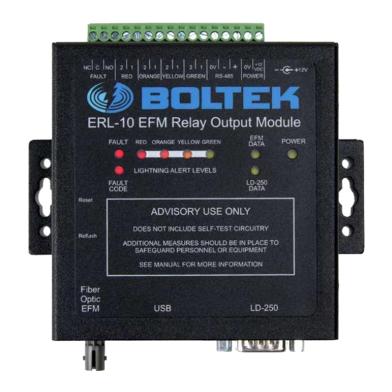
Page 27: Overview
C H A P T E R O V E R V I E W Chapter Overview Front Panel LEDs Figure 15: ERL-10 Top View... - Page 28 O V E R V I E W POWER LED The power LED illuminates when the 12V power is present on the ERL-10. If the LED does not light when the unit is plugged into a power source check your 12V power supply or outlet.
- Page 29 O V E R V I E W FAULT LED The FAULT LED will illuminate and stay on when a problem with the ERL-10 is detected. FAULT CODE LED The FAULT CODE LED will flash a number of times then pause and repeat if there is a failure.
-
Page 30: Usb Messages And Commands
USB Messages and Commands USB/RS485 Messages Electric Field Sentence Transmitted by the EFM-100 twenty times per second over fiber optic or RS485 (as configured by the jumpers in the ERL-10) $<p><ee.ee>,<f>*<cs><cr><lf> <p> - polarity of electric field + or - <ee.ee>... - Page 31 U S B M E S S A G E S A N D C O M M A N D S Strike Sentence Transmitted when a strike is detected within a set distance range. @LI,<ddd>,<uuu>*<cs><cr><lf> <ddd> - strike distance 0-300 miles <uuu>...
- Page 32 LD-250 NO DATA EFM-100 ROTOR FAULT EFM-100 SELF TEST ERROR EFM-100 SYNTAX ERROR EFM-100 CHECKSUM ERROR EFM-100 UNKNOWN ERROR ERL-10 RESET FAULT ERL-10 CONFIGURATION ERROR LD-250 SYNTAX ERROR LD-250 CHECKSUM ERROR LD-250 UNKNOWN ERROR Table 2: Fault Code Data Output.
-
Page 33: Erl-10 Connections
Appendix ERL-10 Connections The following diagrams display the multiple ways the ERL-10 can be wired together with the detectors and computer displays when the default setup is not preferred or possible. Note: Some diagrams are displayed with and without the optional LD-250 long range detector however all connections will work the same with or without the LD-250. -
Page 34: Figure 17: Erl-10 Kit-2 Fiber Optic Input With Serial Server
Remote data access can be achieved with the fiber optic input and serial server connected to the RS485 output on the ERL-10 terminal block. Up to four connections can be made with a single BGW312 serial server, multiple serial servers can be used if more connections are needed. -
Page 35: Figure 18: Erl-10 Kit-2 With Status Monitor And Nexstorm Display
The NexStorm long range display software can be run at the same time using a DB9 Y splitter with one end connected to the ERL-10 and the other end connected to a USB-RS232 adapter plugged into an available USB port. -
Page 36: Specifications
H A R D W A R E S P E C I F I C A T I O N S Appendix Specifications ERL-10 Hardware Specifications Power Supply Voltage: 11.8-18 VDC, 0.8 Amp AC Adapter: 120 VAC, 60Hz (220VAC 50 HZ in Europe) USB Port: 1.0/2.0 Compatibility...
Need help?
Do you have a question about the ERL-10 and is the answer not in the manual?
Questions and answers