
Summary of Contents for JGR PDL 5
- Page 1 PDL5 PDL/IL/BR Multimeter User Manual All information contained herein is believed to be accurate and is subject to change without notice. No responsibility is assumed for its use. JGR Optics Inc, 2014.
-
Page 3: Table Of Contents
PDL5 User Manual TABLE OF CONTENTS COMPLIANCE ......................1 FDA-CDRH C OMPLIANCE .....................1 CSA / IEC C OMPLIANCE ......................1 OMPLIANCE .........................2 GENERAL INFORMATION ..................3 PDL5 PDL/IL/BR M ULTIMETER VERVIEW ................3 EASUREMENTS ........................4 Polarization Dependent Loss Measurement ............4 Backreflection Measurement ..................4 Loss and Power Measurement ................5 UTPUT ........................5... - Page 4 Loss and Reflection issues ................... 38 Long Cables (for single-mode model only) ............39 Laser Stability ......................39 Polarization Controller Issues ................39 STORAGE AND SHIPPING ................... 41 JGR O ETURNING NSTRUMENTS TO PTICS ................. 41 ONTACT NFORMATION ..................... 42 SPECIFICATIONS ....................43 REMOTE CONTROL COMMANDS ................
- Page 5 OMMANDS AND THE OMMAND ........53 IEEE 488.2 Common Commands .................53 SCPI Command Tree .....................54 ESCRIPTION OF NDIVIDUAL OMMANDS ................56 IEEE-488.2 Common Commands .................56 SCPI Commands .....................60 JGR Legacy Device Specific Commands .............69 JGR Device-Specific Command Description ............70 PDL5-UM-00001 Rev 001...
-
Page 7: Compliance
PDL5 User Manual COMPLIANCE FDA-CDRH Compliance Under the US Food and Drug Administration (FDA) Center for Devices and Radiological Health (CDRH), the unit complies with the Code of Federal Regulations (CFR), Title 21, Subchapter J, which pertains to laser safety and labeling. -
Page 8: Compliance
PDL5 User Manual Compliance Electronic test equipment is subject to the EMC Directive in the European Union. The EN61326 standard prescribes both emission and immunity requirements for laboratory, measurement, and control equipment. This unit has undergone extensive testing according to the European Union Directive and Standards. -
Page 9: General Information
PDL5 User Manual GENERAL INFORMATION PDL5 PDL/IL/BR Multimeter Overview The PDL5 PDL/IL/BR Meter is a portable, direct-display instrument that measures polarization dependent loss (PDL), insertion loss (IL), backreflection (BR) and power of single-mode fiberoptic devices (i.e. connectors, components, and systems). The PDL5 multimeter may be ordered with up to four internal laser sources for operation at 1310, 1490, 1550, 1625 and/or 1650 nm. -
Page 10: Measurements
PDL5 User Manual To ensure measurement quality, only calibration jumpers provided by JGR Optics should be used. However, additional measurement jumpers may be supplied by the customer, third parties or JGR Optics. In addition to manual front panel operation, the PDL5 multimetermeter may be operated over the RS-232 serial interface and IEEE 488 GPIB parallel interface. -
Page 11: Loss And Power Measurement
PDL5 User Manual The internal switch and coupler of the PDL5 multimeter enable it to automatically reference out the variations of the internal light source, the signal offset with no light (dark current), and the total signal level from internal and external backreflection (BRtot). -
Page 12: Hybrid Jumper
PDL5 User Manual Extreme care must be taken to avoid damaging the connector when plugging and unplugging the launch cable. Connection must be kept clean and should be inspected before every mating (this means both connectors, the FC/APC on the launch cable and the FC/APC connector on the PDL5 multimeter). -
Page 13: Accessories
PDL5 User Manual Accessories AC power cord FC/APC-FC/UPC hybrid test jumper 1 FC/APC-FC/UPC hybrid calibrated jumper FC-type detector adapter Detector cap MW3 Mandrel Wrap User Manual NIST traceable Calibation Certificate Optional Accessories ... -
Page 14: Safety Information
Failure to comply with any of these instructions or with any precaution or warning contained in the User Manual is in direct violation of the standards of design, manufacturing, and intended use of the unit. JGR Optics assumes no liability for the customer’s failure to comply with any of these safety requirements. -
Page 15: Classification
PDL5 User Manual Classification The PDL5 PDL/IL/BR Multimeter consists of an exposed metal chassis that is connected directly to earth via a power cord and, therefore, is classified as a Class 1 instrument. Laser Specifications The laser (or lasers) contained in the PDL5 multimeter is (are) Class 1 laser(s) as specified under the laser classification of the US Food and Drug Administration (FDA) Center for Devices and Radiological Health (CDRH). -
Page 16: Electrical Shock Hazards
If the equipment is used in a manner not specified by the manufacturer, the protection provided by the equipment may be impaired. Only technicians authorized by JGR Optics should carry out the repairs. In addition to voiding the warranty, opening the unit (even when unplugged) can expose you to potential shock hazards. - Page 17 PDL5 User Manual Some of the unit’s capacitors can be charged even when the unit is not connected to the power source. Do not perform any operating or maintenance procedure that is not described in the User Manual. PDL5-UM-00001 Rev 001...
-
Page 18: Getting Started
PDL5 User Manual GETTING STARTED Caution To avoid injury or death, always observe the precautions listed in “SAFETY INFORMATION” section on page 8. This manual contains complete operating instructions for safe and effective operation of the PDL5 PDL/IL/BR Multimeter. It is recommended that users of the PDL5 familiarize themselves with contents of this manual before using the instrument. -
Page 19: Operational Requirements
Set the power switch to OFF and disconnect the meter. Keep the packaging. Immediately notify JGR Optics and, if necessary, the carrier if the content of the shipment is incomplete, if the unit or any of its components are damaged or defective, or if the unit does not pass the initial inspection. -
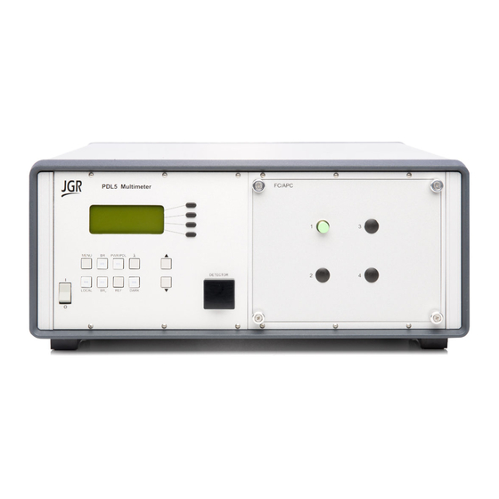
Page 20: Product Overview
PDL5 User Manual automatically switches to a measuring mode in which Pin and Pdark are measured more frequently than every minute and the message “Source Unstable” is displayed. The light sources power is monitored, and the meter returns to the standard measurement mode when the sources have stabilized. Product Overview Front Panel and Key Description A front view of the PDL5 multimeter is shown on Figure 2 and a detailed... - Page 21 PDL5 User Manual Table 4: Rear Panel Components Component Function RS-232C RS-232C serial interface port IEEE 488 (GPIB) GPIB (IEEE 488.1) interface port ~LINE Power Input (also contains the user-replaceable fuse) PDL5-UM-00001 Rev 001...
- Page 22 PDL5 User Manual Table 5: Operating Keys and Status LEDs Key/LED Description ON / OFF Power switch. MENU Used to turn the Menu mode on and off. When deeper menu levels are selected, press the MENU key to step back one level at a time.
-
Page 23: Operation
PDL5 User Manual OPERATION Before the PDL5 multimeter can be used to make a measurement, the user must setup the meter and connect and reference a “measurement jumper” to the front panel connector. Powering Up the Meter To power up the meter: 1. -
Page 24: Set-Up For Br Measurements
PDL5 User Manual Set-up for BR Measurements To prepare the meter for backreflection measurements: 1. Follow the “POWERING UP THE METER” sequence on page 17. 2. Clean the output port on the front of the meter and the FC/APC connector of the measurement jumper (see the “CLEANING THE CONNECTOR ENDS”... -
Page 25: Measuring Br (Including Connector)
PDL5 User Manual ON), the old value must be deleted first by pressing the BR key to turn the BR LED OFF. Pressing the BR button again will store the new value. Repeat the preceeding steps for all other wavelengths at which the measurements are to be made. - Page 26 PDL5 User Manual Figure 5: Measuring backreflection of a connector Figure 6: Measuring backreflection of a connectorized DUT Figure 7: Backreflection measurement area PDL5-UM-00001 Rev 001...
-
Page 27: Measuring Br (Excluding The Connector)
PDL5 User Manual Measuring BR (Excluding the Connector) The method described in the “MEASURING BR (Including Connector)” section is used to measure the backreflection if the DUT is a connector, or if the DUT is a connectorized component and the total backreflection from the connector and the DUT is desired. -
Page 28: Polarization Dependent Loss (Pdl), Loss And Power Measurements
PDL5 User Manual The small amount of reflections that BR0 represent can be polarization sensitive, and multiple reflections can cause interference effects that can make the reflections very sensitive to temperature. NOTE: To ensure accurate backreflection measurements below -65 dB, perform the BR measurement at least once per shift. - Page 29 PDL5 User Manual 7. Press the key to select the desired wavelength. 8. Press the PWR/PDL key to set the meter in ILa and PDL measurement mode. The internal polarization controller will automatically start once this mode is selected. In this mode, the meter displays “ILa”...
-
Page 30: Dark Current Measurement
PDL5 User Manual Dark Current Measurement For loss and power measurements below -50 dBm, it is necessary to perform a dark current measurement (measurement of power with no light). 1. Ensure that the detector is covered, for example, that the detector cap is on or the output connector is connected to the detector. -
Page 31: Measuring Relative Power
PDL5 User Manual Figure 10: Measuring Absolute Power Measuring Relative Power The relative power value displayed by the PDL5 meter is the negative value of the insertion loss, for example -31 dB instead of 31 dB, if the reference was made with the Measurement jumper and the relative power measurement is made with the DUT in-line. -
Page 32: Measuring Ila And Polarization Dependent Loss (Pdl)
PDL5 User Manual Figure 11: Measuring Relative Power (insertion loss) Measuring ILa and Polarization Dependent Loss (PDL) To perform ILavg and PDL measurement, make sure to perform the “SET-UP FOR PDL, LOSS AND POWER MEASUREMENTS” section on page 22 and then, follow these steps: 1. -
Page 33: Power Accuracy
PDL5 User Manual Figure 12: Measuring ILa and PDL Power Accuracy The absolute accuracy of power measurements made with the PDL5 meter is dependent on the power level to be measured. The PDL5 meter does not measure power levels below -50 dBm unless internal electronic noise is measured and its value, described by the dark current ID, is stored. -
Page 34: Mandrel Wrap Technique
PDL5 User Manual Index-Matching Medium allows the light to escape the fiber through the end of the fiber (either bare fiber, or through a connector) with minimal reflections back to the meter. Index Matching Medium can be used on single-mode fiber if expected BR is not lower than -65dB (UPC connectors) and multimode fiber, but since it is less effective than mandrel wrapping, it is usually used on multimode fiber only. -
Page 35: User Menu Operation
PDL5 User Manual Figure 13: Mandrel Wrap Termination Technique Remember also that index-matching technique described below can also be use on single-mode fiber with UPC connectors when expected BR is greater than -65dB. User Menu Operation Accessing the User Menu To access the User Menu, simply press the “MENU”... - Page 36 Options Note REMOTE MENU JGR COMMAND SETs In remote control, the PDL5 Multimeter will be operated using the JGR command set described in Appendix B BAUD RATE: ____ Choose a rate between 300 and 38400 kbit/s Default: 9600 GPIB ADDR: __...
-
Page 37: Messages And Symbols
PDL5 User Manual Messages and Symbols The messages/symbols displayed by the PDL5 meter are shown in Table 7. Table 7: PDL5 Multimeter Display Messages and Symbols Display Description PDL5 VER X.XX Displayed momentarily during power-up sequence and indicates the firmware version. INITIALIZING Displayed momentarily... -
Page 38: Calibration
Calibration should be performed by a qualified Calibration Laboratory. Power and Backreflection values of the PDL5 Multimeter are factory-set and must be periodically adjusted to maintain performance. Calibration Period JGR Optics recommends a 1 year calibration period for the PDL5 PDL/IL/BR Multimeter. PDL5-UM-00001 Rev 001... -
Page 39: Programming Guide
PDL5 User Manual PROGRAMMING GUIDE Setting up for RS-232, USB or GPIB communication The PDL5 Series Multimeter may be remotely controlled via GPIB (IEEE-488) and RS-232 interface. The GPIB interface of the meter conforms to the ANSI/IEEE standards 488.1-1987 and 488.2-1987. The RS232C interface conforms to ANSI/IEEE standard 488.2-1987 where applicable. - Page 40 PDL5 User Manual Table 8: Serial Communication Settings Transmission Rate Selectable in the “User Menu”. Available options are 1200, 2400, 4800, 9600, 19200 and 38400 bps Data bit Parity Stop bits Flow Control None PDL5-UM-00001 Rev 001...
-
Page 41: Maintenance And Troubleshooting
PDL5 User Manual MAINTENANCE AND TROUBLESHOOTING Maintenance Warning Devices with malfunctioning lasers must be returned to the manufacturer for repair. Cleaning the Unit 1. Unplug the unit from the line power. 2. Clean the enclosure with a damp cloth. 3. Do not plug the unit back until it is completely dry. Cleaning the Connector Ends 1. -
Page 42: Cleaning Jumper Connectors
PDL5 User Manual Figure 14: Removing Connector Panel Cleaning Jumper Connectors Warning Connecting damaged or dirty fibers to the unit can damage the front-panel connectors of the unit. Never force an optical connector. Some connectors have a ceramic ferrule that can easily be broken. Optical cable ends need to be cleaned before using them with the unit. -
Page 43: Troubleshooting
7. Using the dusting gas or compressed air, blow the areas cleaned. Ferrule Figure 15: Connector (Connector Type May Vary) Troubleshooting If any problem described in this section persists, contact JGR Optics or your local representative. Connector Issues Front Panel Connectors Follow the maintenance procedure described in the section: “CLEANING THE... -
Page 44: Loss And Reflection Issues
PDL5 User Manual 6. Connect the FC/UPC end to the detector adapter 7. Select Absolute mode 8. Make sure that output power is above -10 dBm for all laser sources 9. Take an IL reference for each wavelength. Select Relative mode by pressing and holding the Power button until zero. -
Page 45: Long Cables (For Single-Mode Model Only)
"WP MOTOR FAIL !". If this message is displayed, there is a problem with the polarization controller. Please contact JGR Optics for support. PDL5-UM-00001 Rev 001... - Page 46 Check the measurement setup HIGH for possible source of light being reflected back to the output port of the source. MOTOR Problem with waveplate Please contact JGR Optics for FAIL ! motor support. communication with the driver board PDL5-UM-00001 Rev 001...
-
Page 47: Storage And Shipping
As indicated above, please ship the returned material in the original shipping box and packing material. If these are not available, follow the guidelines below: 1. Contact JGR Optics to obtain a RMA number; 2. Cover the front panel with foam to prevent damage;... -
Page 48: Contact Information
PDL5 User Manual Contact Information JGR Optics Inc. Phone: 613-599-1000 160 Michael Cowpland Drive Fax: 613-599-1099 Ottawa, Ontario, Canada sales@jgroptics.com K2M 1P6 www.jgroptics.com PDL5-UM-00001 Rev 001... -
Page 49: Specifications
PDL5 User Manual SPECIFICATIONS Specifications are provided here as a reference only and may be changed without notice. Please refer to JGR Optics’s website for the most recent specifications. PDL5-UM-00001 Rev 001... - Page 50 PDL5 User Manual PDL5-UM-00001 Rev 001...
-
Page 51: Remote Control Commands
PDL5 User Manual REMOTE CONTROL COMMANDS Command Syntax and Style Program Message Formats A program message consists of a command header, followed by its required parameters. The parameters must be separated from the command header by a space, for example, *ESE 10. Multiple parameters must be separated by a comma ( , ). -
Page 52: Specifying The Command Path
PDL5 User Manual Specifying the Command Path In order to use a command in the command tree, the meter must know the full path to the command. If the command is the first command in the program message, the command header must contain the full path to the command. Subsequent commands in the same program message are automatically referenced in the same path as the previous command, unless a colon ( : ) precedes the command’s command header, in which case the full path to the... -
Page 53: Implemented Status Structures
PDL5 User Manual Implemented Status Structures PDL5 multimeter has the following status data structures implemented: IEEE 488.2 defined standard registers (standard status structure) The 488.2 standard status structure consists of four registers: status byte register service request enable register ... - Page 54 PDL5 User Manual Bit 0 to Bit 3 are not used. Bit 4 (message available) is set to 1 when a response message is available in the output queue. Bit 5 (event summary bit) is the summary bit for the standard event status structure.
- Page 55 PDL5 User Manual Standard Event Status Register Standard Event Status Register Bit 7 Bit 6 Bit 5 Bit 4 Bit 3 Bit 2 Bit 1 Bit 0 device user command execution query request operation power on dependent request error error error control complete...
-
Page 56: Queues
PDL5 User Manual Bit 7 (power on) is set when an off-to-on transition occurs in the power supply of the meter. Standard Event Status Enable Register The contents of the standard event status enable register determine which events in the standard event status register are reflected in the event summary bit (ESB) of the status byte register. -
Page 57: Error Queue
PDL5 User Manual Response messages are always terminated with the sequence <LF> and, if the response is being sent through the GPIB, the EOI signal is set to true when the last character in a response is sent. If an attempt is made to read the output queue when it is empty and the current program message does not contain a query, a query error bit is set. - Page 58 PDL5 User Manual -240 Hardware error A hardware error was detected, but the control block cannot be more specific. -330 Self-Test error The device failed a self-test. -350 Queue overflow The error queue has overflowed, and an error has occurred that cannot be recorded.
-
Page 59: Ieee 488.2 Common Commands And The Scpi Command Tree
PDL5 User Manual IEEE 488.2 Common Commands and the SCPI Command Tree IEEE 488.2 Common Commands Command Parameter Response Minimum Maximum *CLS *ESE Integer *ESE? Integer *ESR? Integer *IDN? String *OPC *OPC? Integer *RST *SRE Integer *SRE? Integer *STB? Integer *TST? Integer *WAI... -
Page 60: Scpi Command Tree
PDL5 User Manual SCPI Command Tree All commands other than the IEEE 488.2 common commands are listed in the following table. Command Parameters Response [:SOURce] :WAVlength Num Val| MIN|MAX|DEF :WAVlength? None|MIN|MAX|DEF Num Val [:NEXT] :CHANnel Num Val|MIN|MAX :CHANnel? None|MIN|MAX Num Val [:NEXT] [:POWer] :MODe... - Page 61 PDL5 User Manual :CONT? Num Val, String :SYSTem :ERRor[:NEXT]? Num Val, String :VERSion? String :CAPability? String :COMMunicate :GPIB Num Val [:SELF] :ADDRess :COMMunicate :GPIB Num Val [:SELF] :ADDRess? PDL5-UM-00001 Rev 001...
-
Page 62: Description Of Individual Commands
PDL5 User Manual Description of Individual Commands IEEE-488.2 Common Commands Clear Status Command Syntax *CLS Function Clears the following queues and registers: Error queue Standard event status register Status byte register Operation event register Questionable event register If *CLS is sent immediately after a message terminating sequence, both the output queue and the MAV bit in the status byte register are cleared. - Page 63 Function The *IDN query returns a string value which identifies the manufacturer, instrument type and firmware version. Example *IDN? Returns "JGR Optics Inc., PDL5, XXXXXXX, Y.YY" Where: <XXXXXXX> = device serial number <Y.YY> = firmware revision number PDL5-UM-00001 Rev 001...
- Page 64 PDL5 User Manual Operation Complete Command Syntax *OPC Function Causes the meter to set the OPC bit in the standard event status register when all pending operations have been completed. Example *OPC Operation Complete Query Syntax *OPC? Function Places a “1” in the output queue of the meter when all pending operations have been completed.
- Page 65 PDL5 User Manual Service Request Enable Query Syntax *SRE? Function Returns the contents of the service request enable register as an integer that, when converted to a binary number, represents the bit values of the register. Example *SRE? returns 154 if the service request enable register is set to 10011010.
-
Page 66: Scpi Commands
PDL5 User Manual *WAI Command Syntax *WAI Function Prevents the meter from executing any further commands or queries until all previously pending operations have been completed. There are no consequences to this command because all commands are executed sequentially; therefore, any subsequent commands are completed by the time this command is parsed. - Page 67 PDL5 User Manual [:SOURce]:WAVlength? Syntax [:SOURce]:WAVlength?<space>[MIN|MAX|DEF] Function Returns the current or specified output source wavelength in nm No parameter: returns the current wavelength MIN, MAX or DEF: returns the first, last or default wavelength respectively. Example WAV? MIN returns: 1310. [:SOURce]:CHANnel Syntax [:SOURce]:CHANnel<space>[channel_number|MIN|MAX] OR...
- Page 68 PDL5 User Manual [:POWER]:MODe Syntax [:POWER]:MODe<space>[ABS|REL|BRM|PDL] Function Switches the meter between the following operation modes: ABS: absolute power operation mode REL: relative power operation mode BRM: backreflection operation mode PDL: IL avg and PDL operation mode. Example MOD PDL switches the meter into ILavg and PDL mode [:POWER]:MODe?
- Page 69 PDL5 User Manual [:POWER]:DETector[:NEXT] Syntax [:POWER]:DETector<space>[detector_number|MIN|MAX] OR [:POWER]:DETector[:NEXT] Function Switches to the specified detector number no parameter or [:NEXT]: switches to the next detector number detector_number: switches to the specified by the parameter detector number MIN or MAX: switches to the first or last configured detector number respectively.
- Page 70 PDL5 User Manual [:POWER]:BR0:READ? Syntax [:POWER]:BR0:READ? Function Returns the current BR value (custom or factory stored). Example BR0:READ? returns: -65.5. [:POWER]:BR0:STORe? Syntax [:POWER]:BR0:STORe Function Measures and stores the custom BR measurement for the current source wavelength and output channel. Example BR0:STOR measures and stores the custom BR value.
- Page 71 PDL5 User Manual [:POWER]:SVL:READ? Syntax [:POWER]:SVL:READ? Function Returns the current setup via loss value or 0. Example SVL:READ? returns: 0.15 [:POWER]:SVL:CLEAR Syntax [:POWER]:SVL:CLEAR Function Clears the setup via loss value for the current source wavelength and output channel. Example SVL:CLEAR clears the setup via loss value [:POWER]:SVL:CLEAR:ALL Syntax [:POWER]:SVL:CLEAR:ALL...
- Page 72 PDL5 User Manual [:POWER]:REFerence:AWL Syntax [:POWER]:REFerence:AWL Function Takes a relative power reference at current detector with current channel, for all wavelengths. Example REF:AWL takes the reference for all wavelengths. [:POWER]:REFerence:ALL Syntax [:POWER]:REFerence:ALL Function Takes a relative power reference at current detector for all wavelengths and all channels.
- Page 73 PDL5 User Manual :SYSTem:ERRor? Syntax :SYSTem:ERRor? Function Returns the error number and an error message from the error queue. See the Error Queue section, for a list of error numbers and their associated messages. Example :SYST:ERR? returns: 0, “No error”. :SYSTem:VERSion? Syntax :SYSTem:VERSion?
- Page 74 PDL5 User Manual :SYSTem:COMMunicate:GPIB[:SELF]:ADDRess? Syntax :SYSTem:COMMunicate:GPIB[:SELF]:ADDRess? Function Returns the GPIB address. Example :SYST:COMM:GPIB:ADDR? returns 7. PDL5-UM-00001 Rev 001...
-
Page 75: Jgr Legacy Device Specific Commands
PDL5 User Manual JGR Legacy Device Specific Commands Table 10: Device-Specific Command List PDL SPECIFIC COMMANDS Switch to PDL mode PDL? Query PDL value only. Non-triggered command LAV? Query Average loss value only. Non-triggered command Actuate Flip-in Polarizer STATENUM Change the number of polarization states for PDL mode... -
Page 76: Jgr Device-Specific Command Description
PDL5 User Manual JGR Device-Specific Command Description The PDL command will switch the meter to PDL mode. Interface: GPIB and RS-232/USB Syntax: “PDL”<CR> Returned Format: None The PDL? command will cause the meter to transmit PDL? the last PDL value. In triggered PDL mode this command will not initiate a new measurement cycle. - Page 77 PDL5 User Manual The FP? command queries the state of the Flip-In Polarizer. The query returns 0 or . GPIB and RS-232/USB Interface: “FP?”<CR> Syntax: <x><NL> where <x> = 0 (out of the path) or 1 ( in the Returned Format: path) The STATENUM command sets the number of states STATENUM...
- Page 78 PDL5 User Manual The RES? command queries the resolution of the RES? meter GPIB and RS-232/USB Interface: “RES?”<CR> Syntax: <x><NL> where x is the resolution. Valid return Returned Format: values are 2 and 3. The T command sets the meter into triggered or non- triggered(continuous) modes.
- Page 79 PDL5 User Manual The ABS command will switch the meter to absolute power mode. Interface: GPIB and RS-232/USB Syntax: “ABS”<CR> Returned Format: None The REL command will switch the meter to relative power mode. Interface: GPIB and RS-232/USB Syntax: “REL”<CR> Returned Format: None The BRM command will switch the meter to BR...
- Page 80 PDL5 User Manual Query returns the current wavelength number in SWL? “x.x” format, valid returns are 1.3 for 1310nm, 1.4 for 1480nm, 1.5 for 1550nm, 1.6 for 1625nm and 0.8 for 850nm. Interface: GPIB and RS-232/USB Syntax: “SWL?”<CR> Returned Format: <x.x><NL>...
- Page 81 PDL5 User Manual The SCH command can switch the meter to the next channel or to a specific channel Interface: GPIB and RS-232. Syntax: “SCH”<CR> (switches to next channel) “SCH xx”<CR> (where xx = 01, 02, 03,,,,23, 24). Example, “SCH 18” switches to channel 18 Returned Format: None Query returns the current channel number in “xx”...
- Page 82 PDL5 User Manual The BRZS command will store BR . The meter needs BRZS to be in BR mode or dual display mode for the command to succeed. Interface: GPIB and RS-232/USB Syntax: “BRZS”<CR> Returned Format: None The BRZC command will clear BR .
- Page 83 PDL5 User Manual The TMF command will initiate a measurement transmission in full display format addition with current wavelength. Interface: GPIB and RS-232/USB Syntax: “TMF”<CR> Returned Format: Full LCD display plus current wavelength in x.x format. Example: “BR=-60.2dB 1.3” The TDO command will cause the meter to transmit the data only.