Table of Contents
Advertisement
Quick Links
Installation, Operation, and Maintenance Manual
• Failure to follow safety warnings exactly could result in serious injury, death or property damage.
• Make sure to read and understand the installation, operation and service instructions in this manual.
• Improper installation, adjustment, alteration, service or maintenance can cause serious injury, death or
property damage.
• Read the installation, operating and maintenance instructions thoroughly before installing or servicing
this equipment. ALWAYS disconnect power and gas prior to working on unit.
Do not store or use gasoline or other flammable vapors and liquids in the vicinity of this or any other
appliance. Installation and service must be performed by a qualified installer, service agency or gas supplier.
WHAT TO DO IF YOU SMELL GAS:
• Do not try to light any appliance. Do not touch any electrical switch; do not use any phone in your
building.
• Leave the building immediately. Immediately call your gas supplier from a phone remote from the
building.
• Follow the gas supplier's instructions. If you cannot reach your gas supplier, call the fire department.
Some units may contain an energy recovery wheel. By virtue of their design, all energy recovery wheels
allow a level of return/exhaust air and contaminants to be recirculated into the supply airstream. Accepting
and operating this unit with or without the energy recovery wheel in operation increases the risk of airborne
bacteria, virus and contaminant spread between the return/exhaust air, into the fresh airstream.
In accordance with ANSI/ASHRAE/ASHE Standard 170-2017, energy recovery wheel technology should not
be used as a means of ventilation for certain Health Care Facilities. An ASHRAE Position Document on
Infectious Aerosols, approved by ASHRAE Board of Directors, dated April 14, 2020, also recommends that
energy recovery devices be bypassed for non-health care facility ventilation to help reduce the spread of
virus.
Any reduction of outdoor air % or volume below what this unit was designed for elevates the risk of airborne
bacteria, virus and contaminant recirculation back into the fresh airstream and the space.
Operating this unit with an exhaust level less than 50% of the supply level nullifies all return on investment
statements and limits the amount of energy recovery.
This unit, including the energy recovery wheel, must be serviced and maintained as per the Installation and
Operation Manual's recommended frequencies.
Upon receiving unit, check for any interior and exterior damage, and if found, report it immediately to the
carrier. Check that all accessory items are accounted for and free of damage. Turn the blower wheel by hand
to verify free rotation and check the damper (if supplied) for free operation.
WARNING! FIRE OR EXPLOSION HAZARD
FOR YOUR SAFETY
IMPORTANT
RECEIVING AND INSPECTION
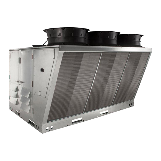
Packaged Rooftop Unit - DOAS RTU Series
A0033507
October 2020 Rev 00
Advertisement
Table of Contents
Troubleshooting

Summary of Contents for CaptiveAire DOAS RTU Series
- Page 1 Packaged Rooftop Unit - DOAS RTU Series Installation, Operation, and Maintenance Manual WARNING! FIRE OR EXPLOSION HAZARD • Failure to follow safety warnings exactly could result in serious injury, death or property damage. • Make sure to read and understand the installation, operation and service instructions in this manual.
-
Page 3: Table Of Contents
Table of Contents WARRANTY ................4 Furnace Start-Up Summary ........... 80 Coastal Applications ............. 4 High Fire Burner Adjustment ......... 80 Furnace Warranty ..............4 Low-Fire Burner Adjustment .......... 81 CERTIFICATIONS ..............4 Final Start-Up Procedure ..........81 Listings and Standards ............4 Sequence of Operation ............ -
Page 4: Warranty
WARRANTY This unit comes with a standard 5-year parts warranty from date of shipment to be free from defects in materials and workmanship, under normal use and service. An extended 10-year non-prorated parts warranty is available at no extra charge when units are remotely monitored and maintained through a Service Preventative Maintenance subscription (terms and conditions apply). -
Page 5: Installation
INSTALLATION It is imperative that this unit is installed and operated with the designed airflow, gas, and electrical supply in accordance with this manual. If there are any questions about any items, please call the service department at 1-866-784-6900 for warranty and technical support issues. IMPORTANT For gas units, to prevent premature heat exchanger failure, do not locate any gas fired unit in areas where chlorinated, halogenated, or acid vapors are present in the atmosphere. - Page 6 CLEARANCE TO COMBUSTIBLE MATERIALS This equipment may be installed with clearances from the equipment to combustible material not less than 0 inches from the top, bottom, condenser side, front and back. The flue side must be installed 3 feet from combustible materials. Refer to Figure 1 for clearance details. SERVICE CLEARANCE For service accessibility and performance, this unit must have at least 3 feet of clearance on the intake and supply sides.
- Page 7 CLEARANCE TO COMBUSTIBLE MATERIALS This equipment may be installed with clearances from the equipment to combustible material not less than 0 inches from the top, bottom, condenser side, front and back. The flue side must be installed 3 feet from combustible materials. Refer to Figure 2 for clearance details. SERVICE CLEARANCE For service accessibility and performance, this unit must have at least 3 feet of clearance on the intake and supply sides.
-
Page 8: Rigging
Rigging WARNING!! Ensure that all the lifting equipment used is properly rated for the weight of the unit being lifted. Each of the cables (chains or slings), hooks, and shackles used to lift the unit must be capable of supporting the entire weight of the unit. Lifting cables (chains or slings) may not be of the same length. -
Page 9: Curb And Ductwork
Curb and Ductwork WARNING!! Failure to properly size ductwork may cause system effects and reduce the performance of the equipment. This unit was specified for a specific CFM and static pressure. The ductwork attached to this unit will significantly affect airflow performance. When using rectangular ductwork, elbows must be radius throat, radius back with turning vanes. - Page 10 Figure 4 - Curb Gasket Curb Attachment Curb Point Side Return Duct/Access Panel Install, refer to Figure 5 Detail A. • Install gasket material around the upper and side edges. • Install ductwork using self-tapping screws. • Use caulk/sealant around the upper and side edges. •...
-
Page 11: Duct Hanger Dimensions
Duct Hanger Dimensions Figure 6 provides details for standard curbs, and Figure 7 provides details for ERV curbs. Refer to Table 3 and Table 4 on page 12 for Bill of Materials and curb dimensions. Use 1/4”-20 x 5/8” Phillips pan head screws and nuts when assembling duct hangers, refer to Figure 8 on page 12. - Page 12 Table 3 - Duct Hanger Bill of Materials Size 1 Size 2 Size 3 Size 4 RTU1DHR = Quantity x 1 RTU2DHR = Quantity x 2 RTU3DHR = Quantity x 1 RTU2DHL = Quantity x 3 RTU3DHL = Quantity x 3 RTU4DHL = Quantity x 3 RTU1DHL = Quantity x 3 NOTE: ERV Quantity x 4...
-
Page 13: Duct Static Pressure Control
Duct Static Pressure Control Units equipped with an Electrically Controlled Motors (ECMs) or Variable Frequency Drives (VFDs) driven supply fan, the duct static pressure control option can be used to monitor duct pressure. 1. Locate where the pressure transducer is installed in the control cabinet. 2. -
Page 14: Typical Submittal Drawing
Typical Submittal Drawing... -
Page 15: Furnace Condensation Drain
Furnace Condensation Drain In some applications, condensation can form in the flue collection box, especially when furnaces are located downstream of cooling coils or operate in a high-efficiency range. If condensation occurs in the flue collection box, there are fittings in the bottom of the flue collection box to drain condensation out of the box. The burner in the unit is provided with a condensation drain assembly located underneath this fitting for the condensation to collect. -
Page 16: Cooling Coil Trap
Cooling Coil Trap There is a field plumbing connection that is required for the DX/cooling coil. This connection is for the drain pan located under the DX/cooling coil. Also, it is recommended that all plumbing connections be sealed with Teflon tape or pipe dope. Install Condensate Trap Assembly to 1”... -
Page 17: Gas
Installation of gas piping must conform with local building codes, or in the absence of local codes to the National Fuel Gas Code, ANSI Z223.1 (NFPA 54) – latest edition. In Canada, installation must be in accordance with CAN/CGA-B149.1 for natural gas units and CAN/CGA-B149.2 for propane units. WARNING: Inlet gas pressure must not exceed pressure indicated on nameplate. - Page 18 Table 5 - Gas Pressure Gas Pressure Type Gas Pressure Inlet Pressure - Natural Gas 7 - 14 Inches WC Inlet Pressure - Propane (LP) 11 - 14 Inches WC Maximum Manifold Pressure - Natural Gas 3.5 Inches WC Maximum Maximum Manifold Pressure - Propane (LP) 10 Inches WC Maximum Minimum Manifold Pressure - Natural Gas...
-
Page 19: High Altitude And Gas Type Orifice Sizing
High Altitude and Gas Type Orifice Sizing The burner orifices should be sized per Table 6 and Table 7, depending on fuel type, furnace size, and altitude. Standard orifice sizes are for sea level. The unit should be ordered with the altitude specific orifices, or the parts should be ordered through the manufacturer (Table 8 on page 20). - Page 20 Table 7 - LP Gas High Altitude Charts LP Gas High Altitude Conversion Size 3 Size 2 and 3 Size 1, 2, and 3 High Altitude for 500,000 High Altitude for 400,000 High Altitude for 300,000 to 50,000 BTU Altitude Input Rate Drill Size Input Rate...
-
Page 21: Lp Conversion Kit For Rtu Series
LP Conversion Kit for RTU Series LP/Natural Gas conversion kits are used to convert from one gas type to another in the field. This kit is used on all RTUs, and the part numbers in Table 9 should be used on furnace sizes listed. Kits contain: •... -
Page 22: Pre-Conversion Unit Check-Out
Pre-Conversion Unit Check-Out The following procedure is intended as a guide to aid in determining that the appliance is properly installed and is in a safe condition for continuing use. It should be recognized that generalized test procedures cannot anticipate all situations. Accordingly, in some cases, deviation from this procedure may be necessary to determine safe operation of the equipment: •... -
Page 23: Gas Conversion Instruction
Gas Conversion Instruction Warning This conversion kit shall be installed by a qualified service agency in accordance with the manufacturer’s instructions and all applicable codes and requirements of the authority having jurisdiction. If the information in these instructions is not followed exactly, a fire, explosion or production of carbon monoxide may result causing property damage, personal injury or loss of life. -
Page 24: Electrical
Electrical WARNING!! Disconnect power before installing or servicing control. High voltage electrical input is needed for this equipment. A qualified electrician should perform this work. Before connecting power to the unit, read and understand the entire section of this document. As-built wiring diagrams are furnished with each control by the factory and are attached to the module’s door. -
Page 25: Building To Unit Power Wiring Connection
Building to Unit Power Wiring Connection Figure 14 - Conduit Termination/Disconnect Switch Wiring Size 3 Unit Shown 208/460/600 V 3 PH. Safety Disconnect Safety Switch Disconnect Switch Gal-flex Conduit Main Power to Unit’s Safety Disconnect Switch Field Supplied from Building Breaker Wiring Fused Disconnect Option First Shelf... -
Page 26: Hmi And Remote Room Sensor Installation
HMI and Remote Room Sensor Installation Remote HMI faceplates (Figure 15), remote room sensors (Figure 16), and smart controls may be ordered and shipped separately. These components measure temperature and assist in controlling the unit. These components should be installed in a safe location, free of influence from external heat sources. Install sensors in areas indicative of the average room temperature, and away from heat-producing appliances. -
Page 27: Typical Wiring Schematic
Typical Wiring Schematic WIRE SHIELDED (I/P) (I/P) IGNITOR SW-15 VOUT SW-16 SW-04 VOUT SW-17 SW-13 VOUT SW-03 VOUT EC1-... -
Page 28: Variable Frequency Drive (Vfd)
Variable Frequency Drive (VFD) WARNING!! - Before installing the VFD drive, ensure the input power supply to the drive is OFF. - The power supply and motor wiring of the VFD must be completed by a qualified electrician. - The VFD is factory programmed, only change if replaced or ordered separately. Consult the VFD manual and all documentation shipped with the unit for proper installation and wiring of the VFD. -
Page 29: Vfd Output Power
VFD Output Power • Motor wires from each VFD to its respective motor MUST be routed in a separate steel conduit away from control wiring and incoming AC power wiring. This is to avoid noise and crosstalk between drives. An insulated ground must be run from each VFD to its respective motor. Do not run different fan output power cables in the same conduit. -
Page 30: Actech Smv Vfd
ACTECH SMV VFD Table 12 - Cross-Reference 1Ø 3Ø Input Amps 1Ø Input Amps 1Ø Output Breaker 1Ø Breaker 1Ø Part Number Volts Input Input 120V AC 240V AC Amps 120V AC 240V AC ESV371N01SXB571 120/240V ESV751N01SXB571 120/240V 16.6 ESV112N01SXB571 120/240V 1Ø... -
Page 31: Make-Up Air (Mua) Board Connectors
Make-up Air (MUA) Board Connectors The Make-up Air Board (Figure 18) is located in the main cabinet, refer to Figure 19 for location. Figure 18 - MUA Board POWER VENT NEUTRAL POWER POWER VENT2 VENT1 R209 C151 R157 0-10 R183 C147 R182 C145... - Page 32 NOTE: Some connections may not be used dependent on system configurations RJ45 connectors Connector J1 and J2 are associated with BMS. Connector J3 through J6 are interchangeable and may be used to connect to an HMI or VFD. J1 - CASLink/Slave J4 - HMI/VFD/Master J2 - CASLink/Slave J5 - HMI/VFD/Master...
- Page 33 Connector J8 contains inputs and outputs for the Flame Safety Controller (FSC) Pin 1 - 24VAC Output to Pressure Switch Input Pin 10 - 24VAC Input from Vent Proving Switch (PSW) on FSC or Electric Heater (option) (J8-1) / Electric Heat Dry Contact Pin 2 - 24VAC Output to Thermostat Input Pin 11 - 24VAC Output (L1) on FSC (TH/W) on FSC...
- Page 34 Connector J11 contains low voltage screw terminal connections BAS/STAT Pin 1 - 24VAC Auxiliary Input Pin 5 - 24VAC Call for Cooling Input Pin 2 - 24VAC Auxiliary Input Pin 6 - 24VAC Call for Blower Input Pin 3 - 24VAC Auxiliary Input Pin 7 - 24VAC Occupied Override Input Pin 4 - 24VAC Call for Heat Input Pin 8 - 24VAC Isolated Common...
- Page 35 Connector J14 contains screw terminal connections AI-2 AI-3 Pin 1 - 24VAC Output to Intake RH Pin 5 - 24VAC Output to Space RH Pin 2 - 0-10VDC Analog Input from Intake RH Pin 6 - 0-10VDC Analog Input from Space RH Pin 3 - 24VAC Common to Intake RH Pin 7 - 24VAC Common to Space RH Pin 4 - 24VAC Common to Humidity Sensor...
- Page 36 Connector J18 contains low voltage connections Pin 1 - 24VDC + Output for Spare Pin 9 - 0-10VDC Analog Output for Mixing Box Pin 2 - 0-10VDC Analog Output for Mixing Box Actuator Pin 10 - 0-10VDC Analog Output for Bypass Actuator Pin 3 - 0-10VDC Analog Output for Bypass Damper/ Damper/Powered Exhaust...
- Page 37 Connector J25 contains low voltage screw terminal connections for DDC Communications Isolated Pin 1 - RS-485 + Pin 3 - RS-485 Common Pin 2 - RS-485 - Connector J26 Programming Port Connector J27 USB Programming Port Connector J28 contains low voltage screw terminal connections DI-2 AI-4...
- Page 38 Connector J30 contains 120V AC connections Connector J31 contains inputs and outputs for components Pin 1 - 24VDC + Output to Outdoor RH Sensor Pin 10 - 24VDC + output to Return RH Sensor Pin 2 - 0-10VDC Analog Input from Outdoor RH Pin 11 - 0-10VDC Analog Input from Return RH Sensor Sensor...
- Page 39 Connector J32 contains inputs and outputs for components Pin 1 - 24VAC Output for High Air Airflow Switch Pin 10 - 24VAC Input from High Airflow Switch Pin 2 - PWM + Output for Exhaust/Power Vent ECM Pin 11 - PWM - Output for Exhaust/Power Vent Pin 3 - 24VAC Output for Proof Of Closure / HE Furnace Float Switch Pin 12 - 24VAC Input from Proof of Closure / HE...
- Page 40 Connector J35 contains low voltage connections THERMISTORS Pin 1 - Suction Line Thermistor Input Pin 6 - Evap/Indoor Thermistor Input Pin 2 - Suction Line Thermistor Input Pin 7 - Condenser/Outdoor Coil Thermistor Input Pin 3 - Liquid Line Thermistor Input Pin 8 - Condenser/Outdoor Coil Thermistor Input Pin 4 - Liquid Line Thermistor Input Pin 9 - Compressor Discharge Thermistor Input...
- Page 41 MODBUS Connector J38 Modbus Pin 1 (A) - Modbus (-) Pin 3 (C) - Modbus Ground Pin 2 (B) - Modbus (+) Dip Switch S1 Switch 1, 2, 3 always OFF. Switch 4 Always ON. If Switch 4 is OFF, BAS terminals disabled. Dip Switch S2 Programming - Service Only Dip Switch S3...
-
Page 42: Optional Components
Optional Components AC Interlock On units equipped with the optional AC interlock, 24V AC power from a rooftop unit should be field wired to screw terminal J11-(5) on the MUA board. 24V AC common from a rooftop unit should be field wired to terminal block J11-(8) on the MUA board. - Page 43 1. Differential Pressure Transducer – Monitors the air pressure differential between two points. This transducer is used in different air control options. 2. 40VA 120V to 24V Transformer (TR-xx) – Verify transformers on schematics. Will vary by application. 3. 20VA 120V to 24V Transformer (TR-xx) – Verify transformers on schematics. Will vary by application. 4.
- Page 44 Figure 20 - Typical Refrigerant Access Panel Heat Pump with Reheat shown Discharge Line...
- Page 45 1. Refrigerant Low Pressure Switch (SW-15) – Detects refrigerant pressure on the low-pressure side of the system. If the pressure drops below the preset value, the compressor will shut down. This sensor has an automatic reset. 2. Suction (Low) Line Pressure Sensor (PS-21) – Pressure transducer that monitors the low side of the refrigeration system.
- Page 46 Figure 21 - Gas Furnace Cabinet Typical Standard Gas Furnace High Turndown Furnace Option 1. Furnace Power Vent (PV-xx) – An assembly used to exhaust flue gases. 2. High-Pressure Gas Switch (PS-03) – Monitors pressure and shuts down heating when pressures rise above the desired set point.
- Page 47 Figure 22 - Typical Burner Cabinet Single Burner Split Burner 1. Ignitor – Powered by Flame Safety Control to initiate light-off. 2. Rollout Switch 1 (SW-05) – Normally closed temperature activated switch. Mounted on bracket at the firing tube. Senses flame roll-out in the event of a blocked tube, low airflow, or low gas pressure. If flame-rollout is present, the switch de-energizes heater circuit on the furnace.
- Page 48 Figure 23 - Typical Damper Access Panel 1. Return Temperature and/or Humidity Sensor (SN-xx) – Monitors the return air temperature and/or humidity. 2. Outdoor Temperature Sensor (SN-xx) – Monitors the outdoor temperature. Located behind outside air intake louvers. 3. Intake Damper Assembly Motor (MT-xx) – Provides control of the outside/return air damper assembly.
-
Page 49: Electric Heater Option
Electric Heater Option The electric coils on the heater are controlled using Silicon Controller Rectifier (SCR) controls. SCR is a time proportioning type controller that modulates the heater and supplies the exact amount of power to match the heat demand. The three black wires from the electric heater will need to be field wired to the disconnect switch. -
Page 50: Compressor Information
Compressor Information Oil return management – Insufficient lubrication can be the result of oil depositing itself in pipes and bends. Return management helps oil deposits to return to the crankcase by: • Increasing velocity for short periods at regular time intervals. •... -
Page 51: Compressor Vzh 088/117/170
Compressor VZH 088/117/170 When oil return management is enabled, the frequency converter performs an oil boost when the compressor is below 3000 RPM (100 Hz). The oil boost will happen every 60 minutes for 30 seconds when the compressor speed is below 3000 RPM (100 Hz). When “Hands On” mode is selected, the oil return management will not be active, even if the parameter is set to be on. -
Page 52: Compressor Drive Information
Compressor Drive Information Refer to Figure 28 for CDS 803 controller interface. Refer to Figure 29 for CDS302/303 controller interface. CDS803 Quick Menu Navigation The parameter setting for the compressor drive is factory set and should not be adjusted unless specified by a service representative. -
Page 53: Cds302/303 Quick Menu Navigation
CDS302/303 Quick Menu navigation The parameter setting for the compressor drive is factory set and should not be adjusted unless specified by a service representative. If replacing the compressor drive, verify the settings match the compressor drive parameter settings. If settings need to be programmed, proceed with the following: •... -
Page 54: Operation
OPERATION HMI Configuration Menu Access Figure 30 - HMI Screen General Overview SPACE The HMI allows the user to change parameters and options. The user may use the HMI to view operating information regarding sensors, 70°F temperatures, pressures, and fault history on the HMI screen (Figure 30). -
Page 55: Configuring Hmi
Configuring HMI To enter the configuration menu (Figure 33), press the bottom two buttons simultaneously on the HMI faceplate. In this menu screen, you may adjust Communication and Advanced Options, check Status, and About information. Figure 33 - Configuration Menu MENU Configuration Communication... -
Page 56: Scheduling
Scheduling To set a schedule on the HMI (Figure 34), you must first enable scheduling: Factory Settings > Occupied Scheduling > On Set your sensor temperature setpoints for occupied and unoccupied schedules: User Settings > Temp Set Points > (Varies) Once scheduling is enabled, and the temperature setpoints are configured, you may enter your scheduled days and times: User Settings >... -
Page 57: Menu Descriptions
Menu Descriptions This section will explain the different menus, settings, and options available in the HMI. Refer to “Menu Tree” on page 67 for default/range settings, and HMI screen navigation. MENU SETTINGS User settings – Allows the user to change or set certain temperatures and configurations on the unit. Any changes within this menu do not require a reboot to take effect. - Page 58 USER SETTINGS Dynamic SP Diff – Temperature differential for dynamic set point change. Dynamic SP Offset – Temperature amount that will change per differential. Dynamic Heat OA – Outdoor air dynamic heat set point. Dynamic Cool OA – Outdoor air dynamic cool set point. CO2 Control Config –...
- Page 59 FACTORY SETTINGS NOTE: Password to enter factory settings menu is 1111 • Heat Pump Config • Cond Fan Config • Mode – The condensing fans can operate from one of the following modes: Outside Temperature Differential or Manual. • OA Diff – If the outside temperature differential is selected, the default temperature is set at 15°F. •...
- Page 60 FACTORY SETTINGS NOTE: Password to enter factory settings menu is 1111 • Cool Hyst • Intake – Intake tempering sensor must change this amount of degrees below the set point before cooling turns off. Default is 3°F. • Space – Space tempering sensor must change this amount of degrees below the set point before cooling turns off.
- Page 61 FACTORY SETTINGS NOTE: Password to enter factory settings menu is 1111 • Low Ambient Cooling – Option that enables the unit to adjust internal parameters and allow cooling operation down to 0°F ambient. On/Off option. • Act Temp – Low ambient logic will activate below this setpoint. •...
- Page 62 FACTORY SETTINGS NOTE: Password to enter factory settings menu is 1111 • PS KP – Proportionally constant value for static pressure measured in V/sec. • PS Hyst – Building pressure must go above or below hysteresis value for fan adjust accordingly. •...
- Page 63 FACTORY SETTINGS NOTE: Password to enter factory settings menu is 1111 • Lock Screen – If the option is set to On, a password (9999) will be required when; screen saver option is enabled or if any button functions are not pressed for 5 minutes. •...
- Page 64 FACTORY SETTINGS NOTE: Password to enter factory settings menu is 1111 • Purge Config • Purge Button – On/Off selection. When enabled On, a purge button will be displayed on the HMI. When the purge button is pressed, the damper will open to max outdoor air and turn on the exhaust contactor.
- Page 65 FACTORY SETTINGS NOTE: Password to enter factory settings menu is 1111 • Exhaust Contactor – This allows the user to assign a contactor for an interlocked exhaust fan. There is an occupied and unoccupied setting for this. • None • Before Airflow: Exhaust fan will start before the airflow proving switch has been activated. •...
- Page 66 SERVICE SETTINGS NOTE: Password to enter factory settings menu is 1234 Temperatures – User can monitor various temperature values. RH Values – User can monitor various RH values. Open/Closed Status – Menu to view the open/closed status of all inputs. Variable Values –...
-
Page 67: Menu Tree
Menu Tree NOTE: If scheduling is On, occupied and unoccupied settings will be available for some RANGE: 35-110°F/2-43°C TEMP SET POINTS INTAKE SET POINTS HEAT (OCC/UNOCC) DEFAULT: 45°F/7°C RANGE: 55-120°F/13-50°C COOL (OCC/UNOCC) DEFAULT: 75°F/29°C RANGE: 40-150°F/4-66°C DISCHARGE SET POINTS HEAT (OCC/UNOCC) DEFAULT: 80°F/27°C RANGE: 40-80°F/4-26°C COOL (OCC/UNOCC) - Page 68 RANGE: 40-150°F/4-66°C OPTION SET POINTS ROOM OVERRIDE TEMP SET POINTS DEFAULT: 90°F/31°C RANGE: 100-300°F/38-149°C FIRESTAT SET POINTS INTAKE DEFAULT: 135°F/57°C RANGE: 100-300°F/38-149°C DISCHARGE DEFAULT: 240°F/116°C RANGE: (-40)-75°F/(-40)-24°C FREEZESTAT SET POINT FREEZESTAT DEFAULT: 35°F/2°C RANGE: 0-40°F/(-18)-4°C CAB HEAT SET POINT CAB HEAT DEFAULT: 0°F/-18°C RANGE: 35-45°F/2-7°C DRAIN HEAT...
- Page 69 RANGE: 0-100% MAN COND FAN SPEED HEAT Adjust OCC only if on schedule. DEFAULT: 100% RANGE: 0-100% COOL Adjust OCC only if on schedule. DEFAULT: 100% RANGE: - 0.0” - HIGH LOW (OCC/UNOCC) PRESSURE CONFIG DEFAULT: 0.00 "WC RANGE: LOW - 5.0 HIGH (OCC/UNOCC) DEFAULT: 0.10 "WC RANGE: 20-80%...
- Page 70 NOTE: Password to enter factory settings menu is 1111. If scheduling is On, occupied and unoccupied settings will be available for some parameters. DISCHARGE, SPACE, TEMPERATURE CONTROL TEMPERING MODE HEAT (OCC/UNOCC) ANALOG, DDC DISCHARGE, SPACE, COOL (OCC/UNOCC) ANALOG, DDC ACTIVATE BASED ON INTAKE/SPACE/BOTH/EITHER/STAT (OCC/UNOCC) ON/OFF...
- Page 71 NOTE: Password to enter factory settings menu is 1111. If scheduling is On, occupied and unoccupied settings will be available for some parameters. When Low Ambient is configured On, the Min Cool OA Temp settings are: RANGE: 50-70 ° F/10-32 ° C COOLING CONFIG MIN COOL OA TEMP MIN TEMP...
- Page 72 NOTE: Password to enter factory settings menu is 1111. If scheduling is On, occupied and unoccupied settings will be available for some parameters. VZH028, 035, 044, 052, 065, COMPRESSOR CONFIG COMPRESSOR MODEL 088, 117, 170 MANUAL/AUTO CONTROL MODE MODE DEFAULT: AUTO RANGE: 212-302 °...
- Page 73 NOTE: Password to enter factory settings menu is 1111. If scheduling is On, occupied and unoccupied settings will be available for some parameters. SUPPLY REF, MANUAL (DEFAULT), EXHAUST FAN CONFIG CONTROL ERV CONFIG 0-10V, STATIC PS ERV ON, ALWAYS ON STAGING DEFAULT: ALWAYS ON RANGE: 0-100%...
- Page 74 NOTE: Password to enter factory settings menu is 1111. If scheduling is On, occupied and unoccupied settings will be available for some parameters. ON/OFF SCHEDULING OCCUPANCY CONFIG DEFAULT: OFF ON/OFF OVERRIDE DEFAULT: OFF ADDRESS UNIT OPTIONS BOARD CONFIG UNIT ADDRESS RANGE: 5-240 S STARTUP TIMER TIME...
- Page 75 NOTE: Password to enter factory settings menu is 1111. If scheduling is On, occupied and unoccupied settings will be available for some parameters. RANGE: 0-60Hz OCC FAN PRESETS PRESET 0-7 UNIT OPTIONS BLOWER CONFIG DEFAULT: VARIES RANGE: 0-60Hz UNOCC FAN PRESETS PRESET 0-7 DEFAULT: VARIES RANGE: 0-100%...
- Page 76 NOTE: Password to enter factory settings menu is 1111. If scheduling is On, occupied and unoccupied settings will be available for some parameters. ON/OFF UNIT OPTIONS MONITORING SENSORS SMOKE DETECTOR DEFAULT: OFF ON/OFF FILTER MONITOR DEFAULT: OFF ON/OFF INTAKE FIRESTAT DEFAULT: OFF ON/OFF DSCHRG FIRESTAT...
- Page 77 NOTE: Password to enter factory settings menu is 1111. If scheduling is On, occupied and unoccupied settings will be available for some parameters. ON/OFF UNIT OPTIONS ROOM OVERRIDE DEFAULT: OFF NONE (DEFAULT), EXHAUST CONTACTOR OCC/UNOCC BEFORE AIRFLOW, AFTER AIRFLOW ON/OFF EXHAUST ON SMOKE ENABLE DEFAULT: OFF...
- Page 78 Password to enter service settings menu is 1234 MONITOR TEMPERATURE TEMPERATURES SENSOR READINGS CURRENT HMI HUMIDITY RH VALUES HMI (1-5) READINGS COMPONENTS INPUT INPUTS OPEN/CLOSED STATUS READINGS COMPONENTS OUTPUT OUTPUTS READINGS COMPONENTS INPUT INPUTS VARIABLE VALUES VARIABLE READINGS COMPONENTS OUTPUT OUTPUTS VARIABLE READINGS BLOWER VFD STATUS...
-
Page 79: Unit Operation
UNIT OPERATION WARNING: Gloves and safety glasses must be worn when servicing refrigeration equipment. Before starting or operating the unit, verify all fasteners are secure and tight. In particular, check the set screw in the wheel hub. Verify power and gas are OFF to the unit. Before connecting the unit to power, turn the fan wheel by hand to verify it is not striking the inlet, or there are any obstructions. -
Page 80: Start-Up Procedure Heating
Start-Up Procedure Heating Furnace Start-Up Summary 1. Open the field-installed manual gas shut-off valve and ensure the On/Off gas control valve knob is set to ‘On.’ 2. Check inlets to all firing tubes on the furnace and ensure that they are all clear of foreign debris. Verify that the tubes line up properly with each nozzle of the gas manifold. -
Page 81: Low-Fire Burner Adjustment
Figure 36 - Modulating Valve and Controls BUTTON 1 BUTTON 2 LED DISPLAY DIP SWITCHES Low-Fire Burner Adjustment 1. Lock the unit into low fire mode. This is achieved by configuring low fire by going into the HMI’s configuration, go to: Service > Test Menu > Test Gas Heat > Run Low Fire Test. 2. -
Page 82: Sequence Of Operation
Sequence of Operation Operation Summary - Gas Heating • When there is a call for heat, the main blower is turned “On” and the airflow switch is proven. • The Flame Safety Controller (FSC-1) sends 120V AC power to the line input of the power vent blower. •... -
Page 83: Flame Safety Control (Fsc)
Flame Safety Control (FSC) The Flame Safety Control (FSC) is present only to monitor the flame, NOT to control temperature. The FSC uses a sensor mounted at the intake of the upper-most firing tube of the furnace to sense the existence of a flame. -
Page 84: Re-Circulating Control Options
Re-Circulating Control Options The ratio of outdoor to indoor air in the discharge supply air can be adjusted through the MUA board output. The board will output a 0-10V DC signal to command the position of the damper. There are several options for controlling the position of this damper. -
Page 85: Heating, Cooling, Defrost, And Reheat
Heating, Cooling, Defrost, and Reheat Figure 38 - Heat Pump with Reheat Option Outdoor Fan(s) Supply Fan Hot Gas Reheat Valve (HG-1) Discharge Line Filter/Drier Discharge High Pressure Refrigeration Reversing Sensor Pressure Liquid Line Pressure Valve Switch Sensor Compressor Electronic Expansion Valve Outdoor Coil Accumulator... - Page 86 Cooling cycle Figure 39 is a basic representation of the cooling cycle. • When the cooling sequence is initiated, the compressor and outdoor fan start. The cooling system is now in operation. Once the thermostat is satisfied, the system will shut down. •...
- Page 87 Defrost cycle (heat pump) • In heating mode, the outdoor (condensing) coil acts as the evaporator coil. Moisture from the outside air condenses on the outside coil, and normally runs off. During the colder part of the heating season, this moisture freezes. This frozen moisture blocks air movement through the coil. A defrost cycle needs to be run to remove the frost.
-
Page 88: Economizer
Economizer Economizer type sets the type of economizer logic that will be used. This feature will control the economizer using a 0-10V DC signal output on the MUA board. The table below shows option selections and definitions. Use the HMI to select Economizer type. Go to Factory Settings > Unit Options > Outdoor Air Config > Economizer. -
Page 89: Psychrometric Chart
Psychrometric Chart Fixed Dry Bulb Economizer Differential Dry Bulb Economizer Di eren al Dry Bulb Setpoint Temp Economizer Band Low Limit Temp Return Temp Min OA Max OA 100% 50% 0% Outdoor Air... -
Page 90: Fixed Enthalpy Economizer
Fixed Enthalpy Economizer Fixed Total Setpoint Temp Setpoint %RH Economizer Band High Limit DP Low Limit DP Min OA Outdoor Air 100% Min OA Max OA Differential Enthalpy Economizer... -
Page 91: Energy Recovery (Optional)
Energy Recovery (Optional) The Energy Recovery (Enthalpy) Wheel is assembled and installed from the factory. Minimal maintenance will provide years of trouble-free service. If the unit is equipped with the optional enthalpy wheel, energy recovery is provided by pulling outside air across half of the wheel and moving exhaust air across the other half. -
Page 92: Drive Motor
Drive Motor The enthalpy wheel comes standard with a variable speed drive motor, which is pre-wired to turn in the proper direction. The motor can adjust speed to lower the enthalpy’s wheel capacity during frosting conditions. This lowered capacity allows the wheel to recover energy still while preventing frosting. During non-frosting conditions, the modulation of the wheel allows enhanced capacity control of wheel for greater turn-down and more precise discharge control. -
Page 93: Network
Network NOTE: The board will reboot when altering certain factory settings. Communication Module (Optional) The Communication Module, PN: SCADA, is included in all CASlink equipped panels. It obtains operational data from various connected components. This communication wiring is either RS-485 shielded twisted pair wiring or RJ45 Cat 5 Ethernet wiring. -
Page 94: Device Instance, Mac Address, Baud Rate
Device Instance, MAC Address, Baud Rate Some applications may require that the Protocessor have a specific Device Instance, the default device instance is 50,000. To change the Device Instance, you must access the Web Configurator by connecting a computer to the Ethernet port of the Protocessor. The computer used must be assigned a static IP address of 192.168.1.xxx and a subnet mask of 255.255.255.0. -
Page 95: Changing The Ip Address
Changing the IP Address Some BACnet IP applications may require changing the IP address of the Protocessor. To change the IP address, go to the internal server by typing the default IP address of the Protocessor, 192.168.1.24, in the URL field of any web browser. The computer used must have a static IP address of 192.168.1.xxx. The window shown in Figure 47 appears. -
Page 96: Ddc Control Points (Bacnet)
DDC Control Points (BACnet) Name Object Type Object Number Function DDCHeatCommand Control/Monitor DDCCoolCommand Control/Monitor DDCBlowerCommand Control/Monitor DDCModulation Control/Monitor DDCOccupied Override Control/Monitor IntakeHeatOccSP Control/Monitor IntakeHeatUnoccSP Control/Monitor SpaceHeatOccSP Control/Monitor SpaceHeatUnoccSP Control/Monitor MinDischargeHeatOccSP Control/Monitor MinDischargeHeatUnoccSP Control/Monitor DischargeHeatOccSP Control/Monitor DischargeHeatUnoccSP Control/Monitor MaxDischargeHeatOccSP Control/Monitor MaxDischargeHeatUnoccSP Control/Monitor IntakeCoolOccSP Control/Monitor... - Page 97 Name Object Type Object Number Function ScheduleTuesdayBEnd Control/Monitor ScheduleTuesdayCStart Control/Monitor ScheduleTuesdayCEnd Control/Monitor ScheduleWednesdayAStart Control/Monitor ScheduleWednesdayAEnd Control/Monitor ScheduleWednesdayBStart Control/Monitor ScheduleWednesdayBEnd Control/Monitor ScheduleWednesdayCStart Control/Monitor ScheduleWednesdayCEnd Control/Monitor ScheduleThursdayAStart Control/Monitor ScheduleThursdayAEnd Control/Monitor ScheduleThursdayBStart Control/Monitor ScheduleThursdayBEnd Control/Monitor ScheduleThursdayCStart Control/Monitor ScheduleThursdayCEnd Control/Monitor ScheduleFridayAStart Control/Monitor ScheduleFridayAEnd Control/Monitor ScheduleFridayBStart Control/Monitor ScheduleFridayBEnd...
- Page 98 Name Object Type Object Number Function ErvWheelSpeed Control/Monitor ErvExhaustFanSpeedOcc Control/Monitor ErvExhaustFanSpeedUnocc Control/Monitor ErvExhaustLowPsSpOcc Control/Monitor ErvExhaustLowPsSpUnocc Control/Monitor ErvExhaustHighPsSpOcc Control/Monitor ErvExhaustHighPsSpUnocc Control/Monitor CO2OverrideHighLimit Control/Monitor CO2OverrideLowLimit Control/Monitor OaResetCoolDischTempSp Control/Monitor DryModeOASP Control/Monitor DryModeCoolSP Control/Monitor PoweredExhaustManPWMOcc Control/Monitor PoweredExhaustManPWMUnocc Control/Monitor CurrentHvacState Control/Monitor CurrentOccupiedStatus Control/Monitor CalculateAverageSpaceTemp Control/Monitor Vfd571ActualFreq Control/Monitor Vfd571MotorCurrent...
- Page 99 Name Object Type Object Number Function EevValvePosition Monitor Only IntakeDpActual Monitor Only SpaceDpActual Monitor Only CompressorPower Monitor Only CompressorFrequency Monitor Only CompressorCurrent Monitor Only ERVExhaustAirRh Monitor Only ERVWheelSupplyPsInches Monitor Only ERVWheelExhPsInches Monitor Only ERVExhCtrlVolts Monitor Only ERVExhAirTemp Monitor Only ERVOutsideAirRh Monitor Only ERVOutsideAirTemp Monitor Only...
-
Page 100: Lonworks
LonWorks LonWorks compatibility (Figure 48) can be implemented on control packages through the ProtoNode, a LonMark certified external Gateway configured to give a Building Management System access to monitor and/or control a list of Network Variables. The ProtoNode is mounted and factory pre-wired inside the Electrical Control Panel. -
Page 101: Ddc Faults
DDC Faults Refer to “Troubleshooting” on page 108 for more information. Code Description Code Description Code Description None MissingSensorDxDischarge HmiMbComm2 FireDetect BrokenSensorDxDischarge HmiMbComm3 SmokeDetect RtcTempSensor HmiMbComm4 SupplyOverload AuxRtcTempSensor DnfsPwrCardTemp ExhaustOverload Hmi0TempInvalid DnfsEarthFault MasterRomCrc Hmi1TempInvalid DnfsCtrlCardTemp AuxRomCrc Hmi2TempInvalid DnfsCtrlWordTimeout FlameProving Hmi3TempInvalid DnfsOverCurrent IntakeFirestat Hmi4TempInvalid... - Page 102 Code Description Code Description Code Description Vfd571Start Vfd571Internal11 ReturnRh Vfd571IncompatParamSet Vfd571Internal12 ErvExhaustRh Vfd571EpmHw Vfd571Internal13 OutsideRh Vfd571Internal1 Vfd571Internal14 Co2Threshold Vfd571Internal2 Vfd571CommModuleFail ErvDoorInterlock Vfd571Internal3 Vfd571Network ExternalInterlockActive Vfd571Internal4 Vfd571Network1 Missing2ndEvapSensor Vfd571Internal5 Vfd571Network2 Broken2ndEvapSensor Vfd571Internal6 Vfd571Network3 ErvSupplyMissingFilter Vfd571Internal7 Vfd571Network4 ErvExhaustMissingFilter Vfd571Internal8 Vfd571Network5 AcbMbComm Vfd571Personality Vfd571Network6 ExhFanContactor1Prv Vfd571Internal10...
-
Page 103: Service Information
SERVICE INFORMATION WARNING: Technicians must be certified by an EPA-approved training and certification program to service any HVAC equipment, regardless of the refrigerant. Basic Service NOTE: Always wear gloves and eye protection when working with refrigerant. NOTE: Purge lines before connecting to service ports. Figure 50 - Refrigeration Service Tools and Service Port Locations Recovery Machine Refrigerant Recovery... -
Page 104: Monitoring With Gauge Set
Monitoring with Gauge Set 1. Close the high side hand valve (red) and low side hand valve (blue). 2. Connect vacuum rated manifold service hoses, refer to Figure 50 on page 103. • Red service hose to the high side service port. •... -
Page 105: Nitrogen Purging
Nitrogen Purging Whenever brazing will be performed in the system, flowing nitrogen through the system is required. This should be done when unsweating connections or brazing new components in the system. Remove Schrader core from the inlet and outlet path for full flow and minimize back-pressure. This step is critical to prevent oxidation and protect the system from contaminants. -
Page 106: Charging An Empty System
Charging an Empty System 1. Connect the manifold service hoses, refer to Figure 50 on page 103: • Red service hose to the high side service port. • Blue service hose to the low side service port. • Connect the yellow service hose to refrigerant source. 2. -
Page 107: Charging System Low On Refrigerant
Charging System Low On Refrigerant 1. To add refrigerant with system running, open the low side hand valve (blue). 2. Start the unit. Verify the unit is in an idle state (it should not be in cooling, heating, reheat, or blower only modes). -
Page 108: Troubleshooting
Troubleshooting The following tables and information list possible causes and corrective actions for possible problems. Review this section prior to consulting technical support. System Troubleshooting Chart Problem Potential Cause Corrective Action Check voltage to the unit. Check the disconnect switch. Unit will not start Power failure Check the circuit breaker. -
Page 109: Hmi Fault Codes
HMI Fault Codes Problem Potential Cause Corrective Action Check wiring. Repair broken or loose wiring connections. Fire There is an input from the fire detector. Replace fire detector. Verify the smoke detector is set up properly. There is an input from the smoke Smoke (optional) Check wiring. - Page 110 Problem Potential Cause Corrective Action Verify supply fan operation, refer to “Start-Up Procedure” on page 79. Signal was not received from air switch Airflow Check damper operation. when supply blower was running. Check airflow switch and tubing at the MUA board. Check connector J7 on the MUA board.
- Page 111 Problem Potential Cause Corrective Action Low oil level, if sight glass is available, check level. Oil depositing itself in pipes. Increase compressor velocity for short periods of The oil level sensor monitors the time. compressor’s internal oil level. Refer to Refer to “Superheat and Subcooling”...
- Page 112 Problem Potential Cause Corrective Action Check Modbus wiring and connections. Verify Modbus address. Verify Min and Max settings of the VFD to Supply VFD Comm Modbus communication fault. the MUA board settings. Go to Factory Settings > Unit Options > Blower Config >...
-
Page 113: Compressor Drive Vfd Troubleshooting Chart
Compressor Drive VFD Troubleshooting Chart Problem Potential Cause Corrective Action Check the cables from the converter to the compressor. There is current from the output Earth Fault phases to ground (earth) in the Check for continuity from the compressor terminals to cables, or the motor. - Page 114 Problem Potential Cause Corrective Action Check the supply voltage and supply currents to the A phase is missing on the frequency converter. supply side, or the mains voltage imbalance is too high. Mains Phase This message also appears for Loss Refer to “Compressor Drive Input/Output (VFD-02)”...
-
Page 115: Compressor Troubleshooting Chart
Compressor Troubleshooting Chart Problem Potential Cause Corrective Action Compressor Shorted or broken wires Use a multi-meter to check the compressor wiring will not start harness for an open or short circuit. Locked rotor Check continuity of the compressor. Replace if failed. Low voltage Test voltage. -
Page 116: Airflow Troubleshooting Chart
Airflow Troubleshooting Chart Problem Potential Cause Corrective Action Replace fuse or reset circuit breaker and Fan Inoperative Blown fuse/Open circuit breaker check amps. Disconnect switch in “Off” position Turn to “On” position. Door switch Verify door is closed properly. Check door switch wiring and switch. Motor wired incorrectly Check motor wiring to wiring diagram located on fan motor. -
Page 117: Furnace Troubleshooting Chart
Furnace Troubleshooting Chart Problem Potential Cause Corrective Action Furnace Does Not Main gas is off Open main gas valve. Light/Stay Lit Shut off valve closed Open shut off valve. ON/OFF gas valve is off Turn ON/OFF gas valve on. Gas pressure out of range Adjust to proper gas pressure. -
Page 118: Superheat And Subcooling
Superheat and Subcooling Table 16 - R410A Pressure Temperature Temperature (°F) Refrigerant Pressure Temperature (°F) Refrigerant Pressure 156.6 10.8 170.7 14.1 185.8 17.8 201.8 21.9 218.7 26.3 236.5 31.2 255.4 36.5 275.4 42.2 296.4 48.2 318.6 341.9 62.3 366.4 70.2 392.3 78.7 419.4... -
Page 119: Component Check/Testing
Component Check/Testing Clogged Filter Switch (PS-10) 1. The vent tube should be connected to the low side port (Figure 51). A fault will occur when the switch senses a negative pressure. 2. If the “Clogged Filters” fault is active: • Check the filters. If the filters are clogged or damaged, replace as needed. Check for any other obstructions in the unit. - Page 120 Low Refrigeration Pressure Switch (SW-15) Figure 52 - Low Refrigeration Pressure Switch 1. For the low pressure switch (Figure 52), insert a back probe tool at connector J36 pin 1 and pin 2. Power the unit ON. Check for voltage at the following pins: •...
- Page 121 Compressor Drive Input/Output (VFD-02) 1. Power the unit OFF. Verify there is no damage to the wiring. Make sure all connections are secure and connected. Verify wiring connections to the schematic. Refer to Figure 54 for details. 2. Verify the unit is OFF. Check for open or short circuits in the wiring harness. 3.
- Page 122 Temperature Sensor Intake (SN-01)/Return (SN-02)/Outdoor (SN-03)/Discharge (SN-04)/Space (HUM-2) Refer to Figure 56 component locations. Check the following: 1. Make sure the unit is OFF. 2. Make sure the wires are connected properly. 3. Measure the resistance of the temperature sensor. Use the temperature/ohm chart to determine your readings.
- Page 123 High Gas Pressure Switch (PS-03) 1. Turn the unit ON. Reset the lever on the switch. Gas pressure must be lower in the chamber for the reset latch to be set properly. 2. Remove the cover. Make sure the wiring is set up for Normally Closed (N.C.) contact (Figure 57). 3.
- Page 124 Vent Proving Switch (PS-01) 1. Verify wiring is connected properly. 2. Check that the vent tubing is routed correctly. Make sure the tube is not pinched or clogged. 3. Verify the bleed hole is not clogged (Figure 59). The bleed hole reduces condensation build-up in the switch and tubing.
- Page 125 Main (On/Off) Gas Valve (VA-01) Figure 61 - Main Gas Valve The main gas valve (Figure 61) is located in the burner cabinet. Units that use 500MBH and larger furnaces are equipped with two shut-off valves internal to a single body. Main Gas 1.
- Page 126 Flame Safety Control (FSC-01) The FSC is located in the main control cabinet. 1. Verify wiring and connections are properly connected (Figure 63). 2. Turn the unit ON. Use the HMI to set the unit in test mode. • Service > Test Menu > Test Heating > Run Low Fire Test > Stages All •...
- Page 127 Intake Damper Motor Assembly (MT-06) 1. Verify the wiring is correct. 2. Check the wiring for open or short circuits. 3. Verify the positive signal from J18 pin 2 is connected to the assembly at pin 3. 4. Verify the negative signal from J18 pin 9 is connected to the assembly at pin 1. 5.
- Page 128 Hot Gas Reheat Valve (HG-1/HG-2) Figure 65 - Hot Gas Reheat Units with a single reheat valve, HG-1 will be a three-way In-Line Valve Three-Way Valve valve. Units that use dual reheat valves will have HG-1 in- line to the reheat coil inlet and HG-2 in-line to the outdoor (condensing) coil inlet.
- Page 129 Power Vent (MT-02) 1. If the power vent motor is not operating properly, power the unit OFF. 2. Verify there is no damage to the vent proving switch or vent tube. 3. Verify there is no damage to the wiring, motor or capacitor. Make sure all connections are secure and connected.
-
Page 130: Maintenance
MAINTENANCE WARNING: DO NOT ATTEMPT MAINTENANCE ON THIS EQUIPMENT UNTIL THE ELECTRICAL SUPPLY HAS BEEN COMPLETELY DISCONNECTED AND THE MAIN GAS SUPPLY VALVE HAS BEEN TURNED OFF. To guarantee trouble-free operation of this unit, the manufacturer suggests following these guidelines. Most problems associated with failures are directly related to poor service and maintenance. -
Page 131: Heating Season
Heating Season • Verify that the drain on the bottom of the flue box in the unit is clear. • Inspect bolts and set screws for tightness. Tighten as necessary. • Inspect the wiring on the unit and replace components where necessary. •... -
Page 132: Coil Cleaning Procedure
Coil Cleaning Procedure Do not use a pressure washer or high-water pressure when cleaning the coil. Always use water to rinse the coil down before using third party cleaning solutions. The use of cleaning solutions and chemicals should be used cautiously; overuse will cause damage to the equipment. If the coil cannot be cleaned with water only, follow the below procedure to clean the coil. -
Page 133: Filters
Filters Table 17 - Louvered Intake Filter Quantity Chart (Washable) Unit Housing Size 16” x 20” x 2” 16” x 25” x 2” 20” x 20” x 2” 20” x 25” x 2” Size 1 Size 2 Size 3 Size 4 Unit Housing Size 16”... - Page 134 Notes...
-
Page 135: Start-Up And Maintenance Documentation
Start-Up and Maintenance Documentation START-UP AND MEASUREMENTS SHOULD BE PERFORMED AFTER THE SYSTEM HAS BEEN AIR BALANCED AND WITH THE COOLING ON (Warranty will be void without completion of this form). Job Information Job Name Service Company Address Address City City State State... - Page 136 Maintenance Record Date of Visit Field Measured Information – Initial Readings Field Measured Information – Final Readings Motor Voltage Motor Voltage Motor Amperage* Motor Amperage* MUA Blower RPM MUA Blower RPM Ambient Wet Bulb Temp °F Ambient Wet Bulb Temp °F Ambient Dry Bulb Temp °F...
Need help?
Do you have a question about the DOAS RTU Series and is the answer not in the manual?
Questions and answers