Table of Contents
Advertisement
Quick Links
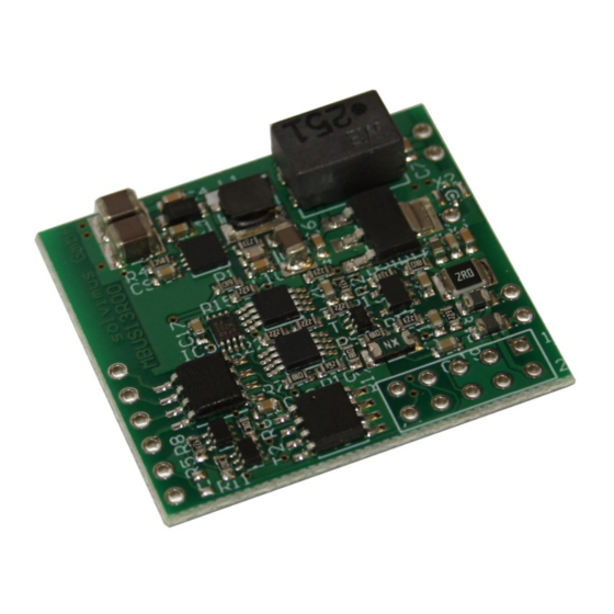
HARDWARE MANUAL MBUS-M13
M-B
OEM
US MASTER
MODULE
MBUS-M13
Version 1.08
Date: 2018-04-05
Author:
Remo Reichel
solvimus GmbH
Ratsteichstr. 5
98693 Ilmenau
Germany
solvimus GmbH – Ratsteichstr. 5 – 98693 Ilmenau – Germany
Phone: +49 3677 7613060 – Fax: +49 3677 7613069 – Email: info@solvimus.de
...we solve.
www.solvimus.de
Advertisement
Table of Contents

Summary of Contents for Solvimus MBUS-M13 Series
- Page 1 MBUS-M13 Version 1.08 Date: 2018-04-05 Author: Remo Reichel solvimus GmbH Ratsteichstr. 5 98693 Ilmenau Germany solvimus GmbH – Ratsteichstr. 5 – 98693 Ilmenau – Germany Phone: +49 3677 7613060 – Fax: +49 3677 7613069 – Email: info@solvimus.de ...we solve. www.solvimus.de...
- Page 2 Hardware Manual MBUS-M13 This page intentionally left blank. Page 2/15 Version 1.08 reichel@solvimus.de, 2018-04-05 HWM_MBUS-M13_1.08_W_EN.docx Draft © solvimus GmbH...
-
Page 3: Table Of Contents
Ordering information ............................13 Wiring diagrams ..............................13 Parametrization of the wM-Bus module ....................14 Reference circuit with collision indication and EMC precautions ........... 15 Altered technical data ............................15 reichel@solvimus.de, 2018-04-05 Version 1.08 Page 3/15 © solvimus GmbH Draft HWM_MBUS-M13_1.08_W_EN.docx... -
Page 4: General Hints And Conventions
The solvimus GmbH will be exempted from any liability in case of changes in hardware or software as well as to non-compliant usage of components. -
Page 5: Font Conventions
Do not use solvents like alcohol, acetone etc. for cleaning. Do not use contact sprays, which could possibly impair the functioning of the contact area and may cause short circuits. reichel@solvimus.de, 2018-04-05 Version 1.08 Page 5/15 © solvimus GmbH Draft HWM_MBUS-M13_1.08_W_EN.docx... -
Page 6: Scope
It is necessary to provide good grounding to personnel, working environment and packing. Electro-conductive parts and contacts should not be touched. 1.7 Scope This manual describes the devices mentioned in the title, supplied by solvimus GmbH, Ilmenau. 1.8 Abbreviations Abbreviation Meaning... -
Page 7: General Information
24 VDC. The internal 3.3 V supply can handle loads with a maximum current consumption of 50 mA. reichel@solvimus.de, 2018-04-05 Version 1.08 Page 7/15 © solvimus GmbH Draft HWM_MBUS-M13_1.08_W_EN.docx... -
Page 8: Pin Assignment
UART Receiver (to RX) UART Transmitter (from TX) Table 5: Pin assignment of connector X1 2.4 Dimensions Following drawing shows the dimensions of the module: Page 8/15 Version 1.08 reichel@solvimus.de, 2018-04-05 HWM_MBUS-M13_1.08_W_EN.docx Draft © solvimus GmbH... -
Page 9: Ordering Information
MBUS-M13-S1 (all pin headers and X1 assembled at the bottom side) 500336* MBUS-M13-M1 (X1 assembled at the bottom side) 500339* MBUS-M13-G1 (X1 assembled at the bottom side) 500340* *delivery only upon request Table 6: Ordering information reichel@solvimus.de, 2018-04-05 Version 1.08 Page 9/15 © solvimus GmbH Draft HWM_MBUS-M13_1.08_W_EN.docx... -
Page 10: Operation
Figure 4: Variant MBUS-M13-S with galvanically isolated interface to external logic Figure 5: Variant MBUS-M13-G with direct interface to external logic Figure 6: Variant MBUS-M13-G powering the external logic (3.3 VDC) on its own (max. 50 mA) Page 10/15 Version 1.08 reichel@solvimus.de, 2018-04-05 HWM_MBUS-M13_1.08_W_EN.docx Draft © solvimus GmbH... -
Page 11: Reference Circuit With Collision Indication And Emc Precautions
Galvanic isolation (variant -S only) 1 kV Environmental conditions for operation 0 ... 50 °C, <95 % humidity Environmental conditions for storage -20 ... 85 °C, <95 % humidity Table 7: Technical data reichel@solvimus.de, 2018-04-05 Version 1.08 Page 11/15 © solvimus GmbH Draft HWM_MBUS-M13_1.08_W_EN.docx... -
Page 12: Timing And Performance Diagrams
12 us approx. 12 us Delay at rising edge approx. 4 us approx. 4 us approx. 4 us approx. 4 us Table 9: Conditions and results of performance measurements Page 12/15 Version 1.08 reichel@solvimus.de, 2018-04-05 HWM_MBUS-M13_1.08_W_EN.docx Draft © solvimus GmbH... -
Page 13: Option Wireless M-Bus
500319 MBUS-M13-G-W MBUS-M13-M-W * available on request Table 3: Ordering information (wireless M-Bus) 4.5 Wiring diagrams The following circuit examples give an abstract on how to wire the module: reichel@solvimus.de, 2018-04-05 Version 1.08 Page 13/15 © solvimus GmbH Draft HWM_MBUS-M13_1.08_W_EN.docx... -
Page 14: Parametrization Of The Wm-Bus Module
(e.g. microcontroller) or with the help of a configuration tool made by Amber Wireless before the module/device is shipped. The module saves the configuration to a non-volatile memory and continues operation with its last configuration after a reset. Page 14/15 Version 1.08 reichel@solvimus.de, 2018-04-05 HWM_MBUS-M13_1.08_W_EN.docx Draft © solvimus GmbH... -
Page 15: Reference Circuit With Collision Indication And Emc Precautions
Bit timing wireless M-Bus 8-N-1 Wireless M-Bus modes S, T, C Dimensions (Variant -S, without pin headers) 30 mm x 33 mm x 10 mm Table 4: Technical data (incl. wireless M-Bus) reichel@solvimus.de, 2018-04-05 Version 1.08 Page 15/15 © solvimus GmbH Draft HWM_MBUS-M13_1.08_W_EN.docx...


Need help?
Do you have a question about the MBUS-M13 Series and is the answer not in the manual?
Questions and answers