Table of Contents
Advertisement
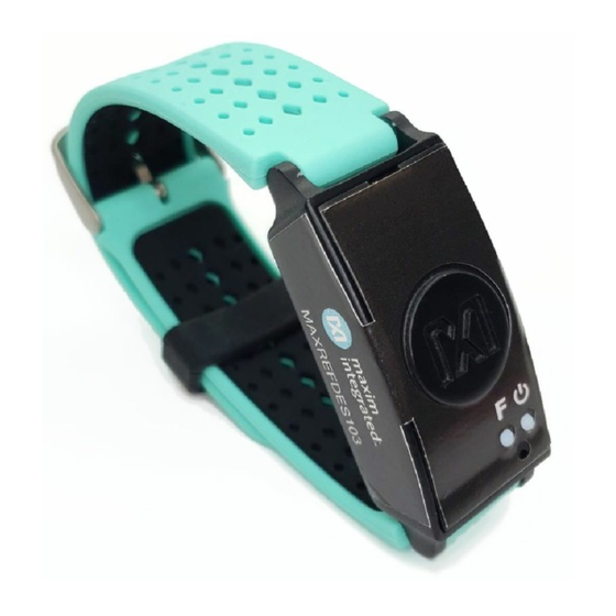
MAXREFDES103# Health Sensor Band
User Guide
UG7145; Rev 1; 1/20
Abstract
This user guide provides information about preparing and running the MAXREFDES103# health
sensor band. This platform uses a high-sensitivity PPG biosensor, power-management IC
(PMIC), and microcontrollers from Maxim Integrated
®
in a wrist-worn design that allows the
capture of biometric signals important to healthcare. The platform also contains algorithms for
calculating heart health based on the biosensor measurements.
Maxim Integrated
Page 1 of 42
Advertisement
Table of Contents

Summary of Contents for Maxim Integrated MAXREFDES103
- Page 1 MAXREFDES103# Health Sensor Band User Guide UG7145; Rev 1; 1/20 Abstract This user guide provides information about preparing and running the MAXREFDES103# health sensor band. This platform uses a high-sensitivity PPG biosensor, power-management IC (PMIC), and microcontrollers from Maxim Integrated ®...
-
Page 2: Table Of Contents
How to Position the Device on the Wrist ................. 10 Software Updates ........................11 Installing the PC GUI ....................... 11 Updating the Micro Board Firmware (.bin) on the MAXREFDES103# ........12 Updating the MAX32664 Sensor Hub Algorithm Firmware (.msbl) ......... 13 Evaluation GUIs .......................... 17 Using the DeviceStudio PC GUI .................... - Page 3 List of Figures Figure 1. MAXREFDES103# wearable form factor in detail............5 Figure 2. MAXREFDES103# system diagram................7 Figure 3. USB Type-C cable (left) and MAXDAP Pico Adapter board (right)....... 8 Figure 4. PPG measurement...................... 10 Figure 5.
- Page 4 Figure 29. Example log file PPG_.csv..................27 Figure 30. Power button on the MAXREFDES103#..............28 Figure 31. MSD connection to PC using USB Type-C cable............28 Figure 32. Flash Log Parser....................... 29 Figure 33. Install the .apk......................30 Figure 34.
-
Page 5: Detailed Hardware Description
USB Type-C Serial Number Button F Power Button Status LED Bottom View Photodiodes LEDs Figure 1. MAXREFDES103# wearable form factor in detail. Required Equipment The MAXREFDES103# platform includes the following components: • Micro board MAX32630 microcontroller • MAX20303 power-management IC (PMIC) •... - Page 6 Bluetooth connection for data streaming and logging ® Android is a registered trademark of Google Inc. USB Type-C is a trademark of Universal Serial Bus Implementers Forum, Inc. Windows is a registered trademark of Microsoft Corporation. Maxim Integrated Page 6 of 42...
-
Page 7: System Diagram
OPTICAL SENSOR (OPTIONAL) HOST ACCELEROMETER LED1 LED2 LED3 GPIO1 USB-C CONNECTOR MAX4740 QUAD SPDT SWITCH LED4 LED1 LED5 LED2 LED6 LED3 Figure 2. MAXREFDES103# system diagram. Arm and Cortex are registered trademarks of Arm Limited. Maxim Integrated Page 7 of 42... -
Page 8: Operating The Health Sensor Band
PC. Both connectors provide power to the MAXREFDES103#. To power off, press and hold the power button on the MAXREFDES103# for at least 15 seconds. Note: If the device becomes unresponsive, a hard reset to the device may be performed by using the power-off and power-on procedures. -
Page 9: Button Functionality
Turn off/on status LED; to power button on the Power Button Power off power on, press for 1s MAXREFDES103# until the LED status turns magenta and blinks fast Start/stop data collection Button F (flash logging) Color Definitions for LED Status Table 2 describes the state of the device for a given color and blinking status. -
Page 10: How To Position The Device On The Wrist
The health sensor band should fit tightly but comfortably around the wrist. Make sure the skin has direct contact with the openings for the LED/photodiodes at the center of the back of the health sensor band. Figure 4. PPG measurement. Maxim Integrated Page 10 of 42... -
Page 11: Software Updates
Software Updates The MAXREFDES103# has been pre-loaded with the firmware that was available during production. A firmware upgrade is strongly recommended to ensure that the most recent set of firmware is loaded. To update the firmware, perform the following steps in this exact order: 1. -
Page 12: Updating The Micro Board Firmware (.Bin) On The Maxrefdes103
3. To flash the host firmware to the MAX32630, drag and drop the .bin binary file into the DAPLINK drive on your PC. 4. The MAXREFDES103# does not automatically reset after flashing the micro board with the new firmware. Press and release the reset button on the MAXDAP Pico Adapter board to restart the health band. -
Page 13: Updating The Max32664 Sensor Hub Algorithm Firmware (.Msbl)
2. Connect the MAXDAP Pico Adapter board device port to the PC using the USB Micro-B cable. Wait five seconds. Device Figure 9. MAXDAP Pico Adapter board device port connected to the PC. 3. Select the Serial over USB/Bluetooth scan option, then click Scan. Maxim Integrated Page 13 of 42... -
Page 14: Figure 10. Maxim Devicestudio Scan Options
Figure 10. Maxim DeviceStudio scan options. 4. Verify that the Devices list in the Connected Devices section shows PPG. Figure 11. Maxim DeviceStudio connected devices. Maxim Integrated Page 14 of 42... -
Page 15: Figure 12. Device Tab To Update The Max32664 .Msbl
Figure 12. Device tab to update the MAX32664 .msbl. 6. Click OK on the Warning! pop-up window. Figure 13. Warning message. The embedded algorithm for heart-rate and SpO measurement is uploaded to the MAX32664 microcontroller on the sensor board. Maxim Integrated Page 15 of 42... -
Page 16: Figure 14. Upload The Embedded Heart-Rate Algorithm To The Max32664
Figure 14. Upload the embedded heart-rate algorithm to the MAX32664. Figure 15. .msbl file flashed successfully. Maxim Integrated Page 16 of 42... -
Page 17: Evaluation Guis
Using the DeviceStudio PC GUI The Windows 10 PC GUI currently supports connection to the MAXREFDES103# through USB or Bluetooth LE. The Windows 7 PC GUI only supports connection to the MAXREFDES103# through USB. Installing the Windows 7 Driver for the PC GUI To use the PC GUI on a Windows 7 PC, installing the driver manually might be required. -
Page 18: Figure 17. Locate And Install The Driver Manually
7. Select Browse my computer for driver software. Figure 17. Locate and install the driver manually. 8. Navigate to the location of the.zip file that was extracted in step 3, then click Next. Figure 18. Browse to the extracted release package. Maxim Integrated Page 18 of 42... -
Page 19: Usb Connection
9. When prompted by the Windows Security window, click Install this driver software anyway. Figure 19. Select Install this driver software anyway. 10. After the driver is installed successfully, the MAXREFDES103# appears as an Mbed ® Serial Port. (The COM port number used may be different from COM4.) Figure 20. -
Page 20: Figure 22. Scan For Available Devices
2. Under Scan Mode, select Serial over USB/Bluetooth, then click Scan. Figure 22. Scan for available devices. Maxim Integrated Page 20 of 42... -
Page 21: Figure 23. Successful Connection Over Usb
3. Verify that the Devices list in the Connected Devices section shows PPG. Figure 23. Successful connection over USB. Maxim Integrated Page 21 of 42... -
Page 22: Bluetooth Le Connection For Windows 10
Figure 24. Scan for available Windows BLE devices. 2. Select the health sensor device for pairing. (The highest signal strength in dBm will usually be the closest health sensor device, and each MAXREFDES103# is labeled with the last four digits of the MAC address). Click Connect. -
Page 23: Figure 25. Bluetooth Le Device Selection
Figure 25. Bluetooth LE device selection. Maxim Integrated Page 23 of 42... -
Page 24: Starting The Ppg Measurement
Value, SpO2 % Completion (for one-shot), Low Signal Flag, Motion Flag, SpO State, and SCD State. 9. Select Log to File and Write Header to save the data to a file. 10. Click Start Monitoring to show the measurement data. Maxim Integrated Page 24 of 42... -
Page 25: Figure 27. Configure For Algorithm Mode
Figure 27. Configure for Algorithm mode. Figure 28. Measurement data displayed. Maxim Integrated Page 25 of 42... -
Page 26: Data Format Of The Log File
SPO2 State 0: LED adjustment 1: Computation 2: Success 3: Timeout SCD State Skin contact state: 0: No decision 1: Off skin 2: Contact with object 3: On skin SAMPLE Time Timestamp in seconds Maxim Integrated Page 26 of 42... -
Page 27: Flash Logging Of Data
1. Click on the three vertical dots near the top right and select the Log to Flash box. If the MAXREFDES103# is still tethered to the PC device, flash logging can be stopped by pressing the Stop button in the GUI or app. Alternatively, Button F may be pressed and released to stop flash logging. -
Page 28: Figure 30. Power Button On The Maxrefdes103
Figure 31. MSD connection to PC using USB Type-C cable. 2. If done correctly, the MAXREFDES103# boots into mass storage device mode. When in mass storage device mode, the MAXREFDES103# will not be able to connect to the PC GUI or Android app. -
Page 29: Figure 32. Flash Log Parser
5. In the PC GUI, open the Flash Log Parser from the Tools menu. 6. Select the .maximlog file, choose an output folder, and click PARSE. A .csv file is generated in the output folder containing the parsed log file. Figure 32. Flash Log Parser. Maxim Integrated Page 29 of 42... -
Page 30: Maxim Health Sensor Platform App For Android
Maxim Health Sensor Platform App for Android Download the latest .bin, .msbl and .apk from the Maxim MAX32664 webpage. Flash the MAXREFDES103# with the latest .bin and .msbl as previously described. Installing the App 1. After flashing the .bin, .msbl, and.apk, install and run the .apk on your Android device. -
Page 31: Optical Heart-Rate Monitoring
1. In the main menu, click Optical HRM. The graphing of the green signal may be seen by deselecting the IR and selecting the Green button. Click the play icon (START MONITORING) in the upper right corner of the app to initiate the heart-rate measurement. Maxim Integrated Page 31 of 42... -
Page 32: Figure 38. Start Heart-Rate Measurement
2. After a brief period, the measurement is complete, and the heart-rate measurement is displayed. Click the stop icon (STOP MONITORING) in the upper right corner of the app to stop the measurement. Figure 39. Heart-rate measurement. Maxim Integrated Page 32 of 42... -
Page 33: Pulse Oximetry
SpO reading, the signals should have peaks and valleys as depicted in Figure 42. If the waveform is not correct, then the strap tightness or health sensor enclosure position may need to be adjusted. Maxim Integrated Page 33 of 42... -
Page 34: Figure 42. Ir And Red Signals Displayed During Spo 2 Measurement
Snr indicates that the signal has a low signal-to-noise ratio. • Motion indicates that movement on the health sensor band is excessive and wrist • movement should be minimized in order to retrieve proper SpO reading. Maxim Integrated Page 34 of 42... -
Page 35: Figure 44. Motion Has Turned Red To Indicate Excessive Motion
Reliable R indicates that the calculated R values are not consistent, therefore SpO • is not being reported. Figure 44. Motion has turned red to indicate excessive motion. 5. Click the stop icon to terminate the measurement. Figure 45. Stop monitoring icon. Maxim Integrated Page 35 of 42... -
Page 36: Heart-Rate Variability
For instance, avnn is selected in Figure 47, and the other measurements are deselected. To start the heart-rate variability monitoring, click the play icon. Maxim Integrated Page 36 of 42... -
Page 37: Figure 47. Start Heart-Rate Variability Measurement
Figure 47. Start heart-rate variability measurement. 2. After a brief period, the measurement is complete, and the data for heart-rate variability is displayed. Figure 48. Heart-rate variability measurement. 3. Click on the stop icon to terminate the measurement. Maxim Integrated Page 37 of 42... -
Page 38: Respiration Rate
Respiration Rate, then click the play icon to initiate the respiration rate measurement. Figure 49. Start the respiration rate measurement. 2. After a brief period, the respiration rate is displayed. Figure 50. Respiration rate measurement. Maxim Integrated Page 38 of 42... -
Page 39: Figure 51. Sleep Quality Assessment
3. Click the stop icon to terminate the measurement. Figure 51. Sleep quality assessment. Maxim Integrated Page 39 of 42... -
Page 40: Notes On The Enclosure
Time-Alignment Method for Comparing PPG Data to ECG Data When comparing the PPG data from the MAXREFDES103# to the data from an ECG reference device, there may be some time differences between the two data sets. Consequently, post-... -
Page 41: Spo 2 Calibration
For calculations used to determine the SpO value and an explanation of how to calculate the coefficients for the end product, refer to Maxim Application Note 6845, Guidelines for SPO2 Measurement Using the Maxim® MAX32664 Sensor Hub. Maxim Integrated Page 41 of 42... -
Page 42: Revision History
Change “Log to Flash” to “Watch Flash” for PC GUI. ©2020 by Maxim Integrated Products, Inc. All rights reserved. Information in this publication concerning the devices, applications, or technology described is intended to suggest possible uses and may be superseded. MAXIM INTEGRATED PRODUCTS, INC.
Need help?
Do you have a question about the MAXREFDES103 and is the answer not in the manual?
Questions and answers