Table of Contents
Advertisement
Quick Links
red-y smart series operating instructions
Handbuch PCU1000
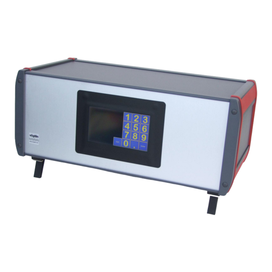
PCU-10 Display and Controll Unit
for red-y smart series
TetraTec Instruments GmbH
Gewerbestrasse 8 | 71144 Steinenbronn
Tel. +49 (0)7157 53 87 - 0 | Fax -10
www.tetratec.de | info@tetratec.de
Vögtlin Instruments AG – flow technology
Langenhagstrasse 1 | 4147 Aesch (Switzerland)
Phone +41 (0)61 756 63 00 | Fax +41 (0)61 756 63 01
www.voegtlin.com | info@voegtlin.com
Advertisement
Table of Contents

Related Manuals for Vogtlin TetraTec Instruments red-y smart Series

Summary of Contents for Vogtlin TetraTec Instruments red-y smart Series
- Page 1 red-y smart series operating instructions Handbuch PCU1000 PCU-10 Display and Controll Unit for red-y smart series TetraTec Instruments GmbH Gewerbestrasse 8 | 71144 Steinenbronn Tel. +49 (0)7157 53 87 - 0 | Fax -10 www.tetratec.de | info@tetratec.de Vögtlin Instruments AG – flow technology Langenhagstrasse 1 | 4147 Aesch (Switzerland) Phone +41 (0)61 756 63 00 | Fax +41 (0)61 756 63 01 www.voegtlin.com | info@voegtlin.com...
- Page 2 red-y smart series Operating instructions PCU-10 for red-y smart series General operating instructions red-y smart meter GSM red-y smart controller GSC These instructions are only valid for smart devices from serial number 110 000 and above Version: PCU-10_E2_1 For the latest information on our products, see our website at www.voegtlin.com ©...
- Page 3 red-y smart series 1.1 Important Instructions Before and installing and operating the instrument it is strongly recommended that this operation manual should be read carefully. Not following the guidelines could result in personal injury and damage of equipment. The content of this manual is provided for information only and may be altered without prior notice. Voegtlin Instruments AG assumes no responsibility or liability for any errors or inaccuracies in this manual.
- Page 4 red-y smart series Toxic, flammable gases and ATEX In the case of toxic and flammable gases, the safety guidelines of the respective country must be followed. The red-y devices are not approved for use in Ex- zones. In the case of flammable and toxic gases, fittings and pipes intended for that purpose must be used.
-
Page 5: Table Of Contents
red-y smart series Contents Introduction Purpose of the Operating Instructions ................... 6 Commissioning Initial Inspection ..........................7 Important Instructions for supplying gas ..................7 Connecting the System ........................7 Main screen Main Screen Offline ........................9 Main screen for MFC-Control ....................... 10 Main screen for Master-Slave ...................... -
Page 6: Introduction
red-y smart series 1 Introduction 1.1 Purpose of the Operating Instructions Working with gases, in particular with flammable and/or toxic gases, requires maximum caution. Therefore reading and understanding these operating instructions prior to the installation and commissioning of the PCU-10 is imperative, so that errors in operation can be excluded. The operating instructions should always be available to operating personnel. -
Page 7: Commissioning
red-y smart series 2 Commissioning 2.1 Initial Inspection The PCU-10 comes programmed and ready for connection. Prior to setup and installation you should check the delivery for shipping damages. If damages have occurred, do not operate the PCU-10. Inform customer service or the manufacturer immediately. The PCU-10 is to be transport- ed using the appropriate means and should be protected from tipping or water damage. -
Page 8: Main Screen
red-y smart series 3 Main screen After you switch on the device the version number of the software installed on the micro-controller is briefly displayed on the screen. In case of malfunction, please mention this number. After that the main screen typical for the set operating mode (Op Mode) appears. The currently selectable operating modes are the normal GSM/GSC controller under the name „MFC-Control“, a master-slave mixer controller under the name „Master-Slave“, a general gas mixer controller under the name „Mixer“... -
Page 9: Main Screen Offline
red-y smart series 3.1 Main Screen Offline The main screen of offline mode displays the following text in the middle of the screen „Offline, MFCs may be handled from other bus controllers“. Apart from that you will only see the „Menu“ button in the lower right corner. The menu, which opens when you select the button, only allows you to set the brightness of the display (Brightness) and change operating modes (Op Mode). -
Page 10: Main Screen For Mfc-Control
red-y smart series 3.1.1 Op Mode Basic operating mode of the controller 0 = Offline 1 = MFC-Control 2 = Master-Slave mixer 3 = General Gas mixer 4 = Burner controller 3.1.2 Brightness Sets the brightness of the display. 3.1.3 EXIT When you exit this window you return to the main screen 3.2 Main screen for MFC-Control In addition to the menu button there are other buttons whose captions give you information about... - Page 11 red-y smart series ensures that these addresses start with „1“ and are sorted in continuous ascending order. You can find more information about this in the section „Registering new MFCs“. When you press one of the buttons the operating parameters for the MFC with this address are displayed.
- Page 12 red-y smart series 3.2.2 STORE Storage function for setpoints (max. 12) – the Store setting has no function in the case of operation with a flowmeter. To save a setpoint, press the Store button – a window opens with the buttons „M1“...
- Page 13 red-y smart series Alarm min. Press / Alarm max. Press Depending on the design of the device the actual value of the pressure in the event of exceeding or falling below the set limits appears in (or if a 24 volt circuit module is connected a switching contact is switched) Menu for selection of the factory calibrating plots stored on the device.
- Page 14 red-y smart series amount in Vol% of total gas. If you are working with a high pre-rarefication, the amount can also be specified in ppm instead of in Vol %. Units Selects Vol % or ppm as the unit for this gas. Controlled For gas mixers which consist of N different channels, the concentrations for N-1 channels are freely adjustable.
- Page 15 red-y smart series 3.2.7 Menu display for MFC-Control When you choose the Menu button in the MFC-Control operating mode the following screen dis- plays: The buttons have the following meanings: Rescan Tests whether all registered devices are really connected and deletes devices that are not present from the main screen.
- Page 16 red-y smart series Additional analogue Input The control board of the PCU-10 has an A/D converter, with which the currents in the range 0/4- 20 mA with high resolution (22 bit) can be measured. In the “MFC-Control” operating mode any parameter can be measured and also displayed. In the operating mode “gas mixer”...
- Page 17 red-y smart series Name The name to be used for the measured value. A complete alpha-numeric keyboard is available for input which allows you to switch back and forth between Upper Case/Lower Case and Special Characters. Units The unit for the measured value, is also set using the keyboard shown above. Format The number format with which the measured value is displayed.
- Page 18 red-y smart series This is the measured value which belongs to the lower calibration value. High This is the measured value which belongs to the upper calibration value. Filter This is the value of a low-pass filter generated by software and indicates the T66 time in seconds. Calibration of the input.
- Page 19 red-y smart series A window opens in which you can then calibrate the input. Here are the settings Accept the current value of the A/D converter displayed in the upper left corner as the low calibra- tion value. High Accept the currently displayed value of the A/D converter as the high calibration value. Reset Resets the low and high calibration values to the default settings.
-
Page 20: Main Screen For Master-Slave
red-y smart series 3.3 Main screen for Master-Slave The ‚Master-Slave“ operating mode combines two devices with sequential addresses into a so- called Master-Slave mixer. Here, the odd addresses are equipped with MFMs and the even ad- dresses are equipped with MFCs. It is the task of the Master-Slave mixer to measure the flow of the MFM and to adjust the flow of the MFC in such a way that the mixing ratio remains constant regardless of the quantity that has been discharged. - Page 21 red-y smart series The following are displayed: Serial number of MFM and MFC Gas type of MFM and MFC Flow range of MFM and MFC Calibrating plot of MFM and MFC as well as somewhat larger: Setpoint of the mixing ratio Actual value for MFM and MFC Total volume flow rate of MFM and MFC Total calculated from the individual totals of MFM and MFC...
- Page 22 red-y smart series Min Flow 1 The actual value of flow 1 appears in if it falls below the set limits (or if a 24 volt circuit module is connected a switching contact is switched) Max Flow 1 The actual value of flow 1 appears in if it exceeds the set limits (or if a 24 volt circuit module is connected a switching contact is switched) Min Flow 2...
- Page 23 red-y smart series Brightness Sets the brightness of the display. Exit Exits the menu Manual Version Page PCU-10 PCU-10_E2_1 © Vögtlin Instruments AG...
-
Page 24: Main Screen Of The Mixer Function
red-y smart series 3.4 Main screen of the Mixer function The Mixer function implements a general gas mixer function, in which case two to four MFCs are combined into one mixer. The names of the gases (automatically read out from the MFCs) appear underneath the column headings as well as the setpoints and PVs (process value) for the 2-4 MFCs, which form the mixer. - Page 25 red-y smart series 3.4.1 Parameter Window of the Mixer function When the gas mixer function is selected, the first 2 - 4 registered MFCs (see: Registration of MFCs) are combined into one mixer. The upper 2-4 buttons on the left side of the window display the gas names that have been read out of the MFCs.
- Page 26 red-y smart series More A second window for the parameterization of the Mixer function opens. Mixer Type Here you can select which of the three mixer types is activated. The numbers mean the following 1 = Standard Mixer function 2 = O2-controlled Mixer 3 = Pressure Controlled Mixer The window has a different appearance depending upon which mixer type is selected.
- Page 27 red-y smart series If an O2-controlled mixer is selected, the window will look like the one shown below. Here are the settings Mixer Type Here you can select which of the three mixer types is activated. The numbers mean the following 1 = Standard Mixer function 2 = O2-controlled Mixer 3 = Pressure Controlled Mixer...
- Page 28 red-y smart series Neg Slope If the O2-limit measured value is fallen short of, the total volume flow rate will be decreased every second by the value specified here, until the condition is no longer given. O2-Limit Limit of the O2-measurement If a Pressure Controlled Mixer is activated, the second parameter window will have the following appearance: Here are the settings...
- Page 29 red-y smart series Max Total Flow The total volume flow rate of the mixer in l/Min, which under no circumstances will be exceeded. Pressure Low This is the lower value of the pressure hysteresis. When this value is fallen short of, it results in the mixture generation being switched on with the total volume flow rate Max Total Flow.
- Page 30 red-y smart series "Not enough flow free for MFC 1 at higher total flow value" "Violation of MFC 2 minimum value at higher total flow value" "Violation of MFC 2 maximum value at higher total flow value" "Not enough flow free for MFC 2 at higher total flow value" "Violation of MFC 3 minimum value at higher total flow value"...
-
Page 31: Main Screen Of The Burner Controller
red-y smart series 3.5 Main Screen of the Burner Controller The Burner Controller is used for the controlled ignition of an oven and its monitoring after ignition. First both MFCs and both solenoid valves are closed. The actual values of both MFCs are dis- played in the bottom left corner of the screen. - Page 32 red-y smart series The big „Start Oven“ button opens both solenoid valves and sets both MFCs to a specified set- point. This setpoint is the one which arises from the parameterization of the burner control- ler for the ignition. The resulting gas mixture is used to ignite the oven. In this phase the screen looks like the one shown above (in reality the MFCs display different numbers than „0“): After the oven is started a seconds counter runs backwards from 16 to 0.
- Page 33 red-y smart series With this the Burner Controller is informing the user that everything is okay and that you can switch to the second gas mixture by pressing the button. The second gas mixture is the one which results from the parameterization of the burner controller for the full load range. After shifting to the second mixture the display changes to: Now the oven can be switched off at any time by pressing the Stop button.
- Page 34 red-y smart series 3.5.1 Parameters of the Burner Controller Pressing the „Para“ button takes you to the parameter settings of the Burner Controller. MFC % Tot @ Ignition MFC1 is responsible for the fuel gas, MFC2 for the oxygen carrier. This setting defines how high the percentage of fuel gas in the total gas flow for the ignition flame is.
- Page 35 red-y smart series 3.5.2 Menu Display of the Burner Controller The menu of the Burner controller is shown in the figure above. The buttons have the following meanings: OP Mode Basic operating mode of the controller 0 = Offline 1 = MFC-Control 2 = Master-Slave mixer 3 = General Gas mixer 4 = Burner controller...
- Page 36 red-y smart series "MFC1 setpoint < 3% range @ ignition" "MFC1 setpoint > range @ ignition" "MFC2 setpoint < 3% range @ ignition" "MFC2 setpoint > range @ ignition" "MFC1 setpoint < 3% range @ full Load" "MFC1 setpoint > range @ full Load" "MFC2 setpoint <...
-
Page 37: Registering New Mfcs
red-y smart series 4 Registering new MFCs The registration of new MFCs to the controller is only possible in MFC control mode. The device has an internal memory with which it can administer 23 VÖGTLIN or BRONKHORST MFCs. The adding or registration of new MFCs to this memory takes place by having an MFC with the MODBUS address 247 in switched off state (delivery state) connected to the device in addi- tion to the MFCs that are already registered and switching the device on afterwards. - Page 38 red-y smart series If you register a device from BRONKHORST, make certain that the lateral rotary switches for the MODBUS address are at „00“. This is the only way PCU-10 can dynamically change the address of the device. Manual Version Page PCU-10 PCU-10_E2_1...
-
Page 39: Repair Instructions
red-y smart series 5 Repair Instructions Repairs can only be made after prior consultation with the manufacturer. All warranties expire in the case of unauthorized repairs, add-ons or retrofitting. 6 Installation Guide for Panel Mount Version View from the front on the touch screen from operator side. All dimensions are mm. Front ribbon cable opening Caution: the ribbon cable must be placed as indicated. - Page 40 red-y smart series Dimensions of the front cut out including 4 drillings: The four pre installed distance pins are planned for a front wall thickness of 2 mm und should be adjusted to the actual wall thickness. Front and side view: Manual Version Page...
- Page 41 red-y smart series J2: analog input: 1,2,3 P6, P7, P8 connector for RS485 for 24 volt connector Connector sockets on the display pcb: J1: 24 Volt connector, the included black and red cable adapter (black - / red +) is pre configured and has to be connected to the included power supply V- and V+.
- Page 42 red-y smart series SUB D connector table Manual Version Page PCU-10 PCU-10_E2_1 © Vögtlin Instruments AG...
Need help?
Do you have a question about the TetraTec Instruments red-y smart Series and is the answer not in the manual?
Questions and answers